Continue to Site

Welcome to our site!

Electro Tech is an online community (with over 170,000 members) who enjoy talking about and building electronic circuits, projects and gadgets. To participate you need to register. Registration is free. Click here to register now.

  • Welcome to our site! Electro Tech is an online community (with over 170,000 members) who enjoy talking about and building electronic circuits, projects and gadgets. To participate you need to register. Registration is free. Click here to register now.

:: Common Grounds? ::

Status
Not open for further replies.

suby786

New Member
:: Common Grounds? - NEW INFO WITHIN::

Hey there

im programming my PIC16F877A on a breadboard using ICD2 and a suported programmer...(which is powered by USB)... when i power the WHOLE BREADBOARD by my 5way ICSP connector its fine,and as i am interfacing to my pic...serial communication thru the form of a USB->SERIAL adaptor...and then taking the TRANSMIT pin to my RX pin... and the ground pin of serial plug to my BREADBOARD gnd... it all works fine... i can send hex values over 2my pic without a problem.

The reason i believe is becuase the USB ground is its COMMON GROUND...hence it works...

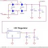
BUT for my project i will b powering through 240v - down to 5v... and when i plug "my" 5v power supply to the board, along with the serial line and its asscoiated ground, the pic doesnt like it... this is not just due to my pwoersupply, off the shelf 5v power supplies i have tried, with the same effect, the pic will only like it if its POWERED by the same GND as the transmission..

anyway around this?...for testings my transmission is wired... but in the end its gonna be an RF link... so my problem MAY be solved when i do this?

as i will have the transmitter on a small pcb board connected to the USB port of the pc...and the RF reciever will be powered by "MY" powersupply... does this make sense to you?
 
Last edited:
There should be no problem with a common ground between your 5v supply and the ground of the system, either yours or the PC's
Make sure that you are not laying down power to the USB or serial busses anywhere. When your circuit is powered externally, do not try to power it from the USB bus at the same time.
 
cherrs mate

i know i not connecting 2 power sources...

but when i externally power my ckt it works fine, except the transmission... the SERIAL port needs a GND reference for its -10/+10 voltage swings... and when i supply it with MY 5V GROUND... it transmits, as i have transmit/recieve led's but the pic doesnt like it enough 2 display what i have sent...as soon as i power the board via USB ICD2 debugger, the communication is all dandy...which must be due to the differences in grounds...?????????????
 
I can't really help you further unless you can post a schematic, you really shouldn't have a problem having a common ground, providing you are not laying down power to any of the transmission lines. I assume that you do have sufficient decoupling etc in your circuit and in your power supply etc ?
 
here is the power schematic im using...

the ground (the triangle) im using is whats going to PIN 5 of the SERIAL CONNECTOR that goes to my PC... (USB>SERIAL ADAPTER)...

the TRANSMIT pin of my dongle is going to an input on the MAX233A chip...which is also powered by this same ground...
 

Attachments

  • decoupling.JPG
    decoupling.JPG
    43.5 KB · Views: 130
is this USB > Serial convertor one of those leads with a bump in the middle ?

or do you have a USB > Serial convertor on board ?

The power supply looks ok, although I would want at least a 100uF cap on the output of the 5V reg

Post a complete schematic of your project if you can, so that I can see if you have something hooked up incorrectly

If essentially all you have onboard is just a serial port (Max233) and you're using one of those convertor leads, I see no problem with a common ground.
 
the lead is a length of wire... with a usb connectioon on 1 side...and 1m down the line, it has a hefty serial connection...with eletronics within its case... at this point i connect my 9way plug into this...and at the back of this plug...is pin 2 or 3 (cant remember - the transmit pin) and pin 5 which is the GND pin...

the GND pin is connected to my BREADBOARD ground...and TRANSMIT pin is connected to MAX233A RS232 input pin...

ill post up a schem when i finished drawing a representative 1...

maybe the ground from the USB is different slightly to the ground of MY OWN POWER SUPPLY/and the off the shelf power supply... (which is a plug adapter that u can set to 5/6/8/9/12/15 VOLTS... it doesnt like when i use that either... ONLY WHEN POWERED BY USB... hop thats helped a bit?
 
I suppose it's possible, although I don't see any real reason for it, to have the ground isolated in the converter between USB and serial interface, in which case you don't actually have a common ground to the PC. Check that the ground is actually continous between each end of your conerter lead. I know these converter leads can cause headaches with what end powers the converter etc though, because I have been unfortunate enough to have been caught out with two of them before. I still don't see a problem with a common ground in the circuit though, assuming that the USB ground is the same as the PC ground.

Your power supply on your board is well enough decoupled ?
Have you checked your plug in power supply for an AC component being superimposed on the DC ?
 
hey mate..

i sorted out my problem now...feel a bit stupid and n00by lol...

on my PSU i had a 47u and 100n cap AFTER THE regulator on my seperate board...

on my breadboard i had ANOTHER 100n decoupling capacitor that was there when i started... once i remove that cap on the breadboard...the ckt works just how it does in USB power mode...no common ground issues...

cheers mate...

so a ckt maybe TOO MUCH decoupled...remember this folks lol - i didnt until today and i did a whole EMC module.. lol
 
suby786 said:
so a ckt maybe TOO MUCH decoupled...remember this folks lol - i didnt until today and i did a whole EMC module.. lol

I don't think an additional 100nF capacitor on the power rail will make or break a project. Thus it cannot be the real reason to your problem. Your problem is gone for some reasons, might be very likely an intermittent one.

Put the capacitor back and watch the circuit works nonetheless. If the circuit stops working with the cap, you have more serious problem in your circuit than you have realised.
 
yeh mate im sorry2say u are RIGHT... after more vigorous testing, there is still a problem, looks VERY VERY intermittent... but the addition of the 100n cap on the breadboard makes a huge difference...if its there then the pic doesnt like it and doesnt output anything... the pic boots up as i have a reset light sequence from the same led's

i did a test WITH usb power... and it worked perfect, i did the EXACT same test with my power supply and 95% of the time it worked the same, but sometimes it did mess up a bit and made other outputs come on randomly...

so where could my underlying problem be? it must be to do with coupling of the power lines, if the 100n had so much of an effect, maybe i need a smaller cap? what would you suggest i start looking at mate..
 
I mentioned to you that I would change the 47uF to at least 100uF on the output of the regulator...have you tried that ?
 
Status
Not open for further replies.

Latest threads

New Articles From Microcontroller Tips

Back
Top