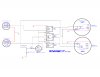
I'm going to give you some hints. The ground symbol has to go, but I admire you TRYING really hard to convey the positive ground notion. Use the open triangles that point UP. That will designate that it's a common. For like -6 just use an arrow. e.g. -BAT or -IGN.
Thanks, I just tryed to use some std symbols from the library. I've never used Design Spark software so I have a steep learning curve...
Just a note: I tend to over think. Any idea is worth presenting.
I appreciate your over thoughts...
There is definitely something wrong with the RF LED and RL1b
If you hunt around, you may find 6V automotive LED lamps. You might find it easier to work with it as a negative ground system and then flip it. The standard flasher won;t work. You'll have to create one. It used power draw of the lamps and heating, You had an added effect, when a lamp or more burned out the blinkers won't flash. The flasher also has to make NOISE.
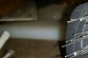
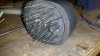
The lights themselves are custom made to hold the LEDs and fit inside the old housings. I didn't shown the flasher but will pick up an electronic 6 volt motorcycle flasher or add some resistance in series. The circuit is just for me to prove out a way to use all the LEDs in the array without having some light up for each function.
I see two options 1) relay/diodes/flash module and 2) Your own sort of BCM module and 3) A BCM module with lamp fail detection. You could look at
www.picaxe.com . Again, not your question,
I did try using a commercially made product for combined trailer lights run from a modern car with separate signal and brakes. It didn't work with reverse polarity.
Four way flashers is an option and so is the third brake light. There were kits to add 4-ways way back when and there were kits to add a third brake light. JC Whitney comes to mind. I think they used like a 4PDT slide switch and a separate flasher, but do brake lights override?
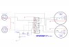
The 4 ways are handled in the signal light switch. Sorry I didn't show that in the circuit as it is existing.
So relays of the SPDT. DPDT or ever 4PDT could be used in your design, with diodes doing ORing of signals and for coil transient suppression.
That said, it's a complex beast if you include 4 ways and a 3rd brake light. You didn't.
No 3rd brake light either. Shes 65 years old and I just want it to look original even though they didn't come with signal lights either ...
I'd look at the design as:
The turn signals overide for the front. Blinking is LEFT or RIGHT sides of the car. e.g. left turn, right turn
so, you get; the parking light circuit provides the power to the front lamp if not blinking.
Don't need park lights for the front. They exist separately.
and you get
The brake circuit provides power to the brake lamp if not blinking for the rear.
parking is a separate bulb. Corrolary: You need to provide a LEFT and RIGHT brake signal from the single brakes signal.
4-way flashes left and right sides. Brake overides rear bulbs or a per bulb basis.
Third brake is from left or right brake. i.e. you might have to separate the brake signal into left brake and right brake. because the turnsignals are operating the "sides" of the car,
That does mean you'll have to come up with some logic to direct the turn signals and select/de-select the hazzard mode and provide flash and make noise.
I will mount all these relays under the dash so there may be some noise there.
So, the key is creating left an right brake signals which are compatible with left turn/right turn,
One other headache is that Hazard is powered from -BAT and turn from -IGN OR -IGN disables turn.


")