Continue to Site

Welcome to our site!

Electro Tech is an online community (with over 170,000 members) who enjoy talking about and building electronic circuits, projects and gadgets. To participate you need to register. Registration is free. Click here to register now.

  • Welcome to our site! Electro Tech is an online community (with over 170,000 members) who enjoy talking about and building electronic circuits, projects and gadgets. To participate you need to register. Registration is free. Click here to register now.

coilgun

Status
Not open for further replies.

mynameisdan

New Member
Hello there,
I just revived my account, and what a crappy name i have -.- ah well.

From a few years ago (on this site) there was someone called "SomeoneElectro" I think that's right, who made a coilgun. I'm now making my own.

I want to go a stage further, though. I bought 40,000uF@63V worth of capacitors to bank together (1000uF each). I am worried about the discharge on these things and don't know how to work out the power or amps.
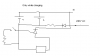
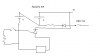
I don't want to put these into an almighty bank and fire them all at the same time. I want to fire them in stages. So my first thought, 4*10,000uF caps @ 63V with a SCR for each bank. How do i work out the current (assuming a low resistance on the coil) at 50 volts?

My second thought, if i fire in stages, instead of all in one go, will this benifit me? would it be better to pump all that current into one wire? maybe wire a the caps into 2 banks for 120V or 4 banks at 240. Although the SCRs i bought were rated at 200V.

If i fire in stages, the projectile would be accelerated 4 times instead of just the one and may go faster. Although timing would be critical and may be hard to get right.
 
Big coil guns are problematic, but always multi stage. The currents involved in doing a 'big' gun in a single shot don't work out so good (Heating occurs in a resistor at the square of the current passing through it) Short pulses at the right spot during the projectiles travel work best. Usually these stages are optically triggered. Getting them to work passably is difficult, fine tuneing them is an art.
 
Last edited:
I have a working coilgun now, single stage, though. It has very little power, I'm trying to make it higher voltage and arange the caps diffrently. I hope it works better.

Still waiting on the thyristors, though. Since the ones i have are rated at 200V, i plan to use about 600v
 
remember that when you have a ferous object being pulled into a coil, that any current left running throught he coil after the object has reached the half way point will cause drag. But, the closer you get to the center with the object before power is cut, the more powerful your gun. To pull this off you need precice timing, some sort of sensing device to know where the projectile is, and a way to compensate for the lag caused by your electronics.
 
Thanks for all the help. The working gun (without SCR, i was having some problems) is here.

https://youtube.com/watch?v=L5Q-lMuJ6kY

The first one i made, with SCR and electronics:

https://youtube.com/watch?v=CPSY05O0Vsg

My first one was working at 54volts. The second one is working at 480. I acheived this quite simply. 2 capacitor banks each hold 240 volts. Charge them in parallel, discharge them in series. Capacitor charge pumps work on the same principle i belive.
 
Am I the only one who used a Xenon flash tube to switch the high currents? Mind you, mine was a rail gun, not a 'lil coil gun :D

If you are willing to go higher in voltage (remember in cap storage energy goes up to the square of the voltage) then a spark gap trigger may be in order..or perhaps I'm going over the top here. Its simple, effective, sharp rise time but you'll need some sound proofing.

Hmm I think I'll try and make one myself, as I haven't done it since I was 13..maybe I could increase the woeful efficiency (<1%) of them?
 
I'm using a 25amp 800v SCR and it doesn't even get warm.

I am planning on adding another capcitor bank which will duplicate the one on it. Where i charge it to 240V then put it in series for 480V except i will put it in series with the other bank for 960V. I'm hoping to be able to use a small switch to do all of that for me, instead of changing wires.
On another note, can someone help me design a circuit that will detect 240volts and light up an LED? I tried using a 555timer and a large resistor but with no luck. I want something really simple. maybe something like the flash indicator on a camera.
 
You could just search for 'comparator' on google.

You set a 'reference voltage' on one pin....then the voltage you wish to compare it to on the other, the output will change state when the input goes above/below the reference.

Obviously, a comparator like the lm393 (which has 'two' comparators in it) cannot take 240v, so a suitable voltage divider would do..to get it down to, say, 10v. Then set your reference at 10V and bobs your aunties brother :)
I'm not sure of the VVC range, but I'm sure it'll go from 12v.

Maybe not as simple as a 'transistor', but comparators are cheap.

Failing that, a (not very accurate) method would use CMOS logic, as these have a set transision voltage for a 0 or a one...usually VCC/2. That is, an inverter (4069?) will output a 'low' when its input goes above 2.5v. So for 240v you'll need a voltage divider of about 96. (470k, 4.7k?)

The 'flash indicator' on a camera is a simple neon lamp, usually connected across the charging cap via a voltage divider (and current limiting resistor) resistor. It lights at about 90v (ish) so if the voltage divider has a ratio of 3:1, it wll light up when the cap reaches 270v charge. Simple, but relatively effective.

The comparator idea would be far more accurate, but if your caps are rated at 120v...and you charge two in series...I wouldn't go for 240v...thats pushing them at their limit :D
 
Putting capacitors in series is unsafe, but i have no choice since my supplier only stocks capacitors up to 450V at 1uF so they're no good. the best is 63v at 1000uF. I have 4 of them in series then in parallel. Thanks for the comparitor idea, i'm ordering a few now.

I have found a problem, I have a "leak" somewhere. When i put the capacitors in series (after they are charged) to gain 480V they are discharging quite rapidly. So i have to switch over and fire pretty fast. The SRCs start getting hot as soon as i switch over. They are rated at 800V so i don't see a problem.
 
Perhaps you could post a rough schem of what your setup is?

As for caps, I'm by no means a 'seasoned' coilgun maker, I just used to mess about when I was younger...but I found photoflash caps were great. 330v 100-800uF and remember, the energy stored in a cap is E = 1/2 C (V^2). Obviously a 1uf isn't going to do much, but plug some values into that equation to workout the best cap.

Without a diagram, I can't say where the 'leak' is....of course caps do lose some energy, but not very quickly, you must have a diode in series with the charger, otherwise they'll discharge back through the charger (not good) but I'm sure you know that anyway.

Unless you have something across the caps leaking current, i don't see what the problem could be. I know everyone uses SCR's for these things, but I was always worried about any 'high current' switch, even if the discharge time is in sub miliseconds time...the current peak is huge.

BT
 

Attachments

  • charging.PNG
    charging.PNG
    5.3 KB · Views: 192
  • fireing.PNG
    fireing.PNG
    5.3 KB · Views: 197
mynameisdan said:
Putting capacitors in series is unsafe, but i have no choice since my supplier only stocks capacitors up to 450V at 1uF so they're no good.

No, it's perfectly safe if you do it correctly, you should use balancing resistors to ensure the voltage is spread evenly - many PC power supplies use this technique, with two capacitors in series for 230V, and wired as a doubler for 110V.
 
I've had an idea.
The capacitors i have, if put in series (all of them) can output 2400 volts. Which is ideal for my coil. So when i get the chance to order some parts that's what i'm going to do. I can make a simple contactor with a solenoid to fire it. Instead of messing around with SCRs.
 
Be careful with a 'simple contactor'...even with relatively small cap bacnk (800uf @330v) I have done some impressive 'welding'. Including getting a phillips screwdriver firmly melted onto the cap terminals.

For 2kv+ may I suggest a spark gap trigger? It is probably a bit over complicated, but it involves three ball terminals, in a line, placed with a mm gap between each one. The first is GND, the second goes to your coil (the other end of the coil goes to the cap bank +V) and the third is the 'trigger'.

A 6kv trigger from either a camera flash trigger (goes to teh centre of the xenon tube) or....one of those little peizo ignition lighters. It will discharge to ground (the first terminal) so it will arc across to the middle terminal, then the gnd terminal. This ionises the air between the firswt and second terminal, creating a path of relatively low resistance, so the cap discharges through this, into the coil. Plus, as an added bonus, it sounds mental.

This only really works with higher voltages generally 1.5kv+ but because you are using aspark trigger, no welding will occur, and it'll be a fantasticly small rise time, which, depending on your coil gun setup, can be a good thing, or a bad thing.

At least thats something to think about...by all means use a solenoid, but if you do the maths, you can work out the peak current or wattage going through that contact...it'll be huge! You'll want to cover it for safety reason, don't want little bits of hot metal flying everywhere.

BT
 
I did think about a spark gap, but this came to mind "how the hell am i going to generate enough voltage to ionize a mm of air?". You gave me the perfect simple answer, a pizo squishy thingy out of a lighter.

Thank you :)
 
Status
Not open for further replies.

Latest threads

Back
Top