Continue to Site

Welcome to our site!

Electro Tech is an online community (with over 170,000 members) who enjoy talking about and building electronic circuits, projects and gadgets. To participate you need to register. Registration is free. Click here to register now.

  • Welcome to our site! Electro Tech is an online community (with over 170,000 members) who enjoy talking about and building electronic circuits, projects and gadgets. To participate you need to register. Registration is free. Click here to register now.

CMOS pump control circuit problems

Status
Not open for further replies.

electrookie

New Member
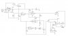
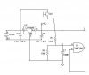
As I figured, I’m back again looking for help. This is a circuit I have been working on for several weeks or more and presented it previously with a different problem that was resolved by help from you in this forum. It has change to what is attached now and I am having other problems with it. If you can help me figure this out, it would be appreciated greatly, to say the least.

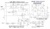
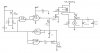
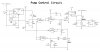
It is for controlling a pump. The idea is the pump is allowed to run for 3 to 5 seconds when the 1st clock of the 4528 is active (3 to 5 sec.). When the 1st clock times out, the 2nd clock starts and looks to see if Sw1 is still closed. (Sw1 is a float switch). If Sw1 is still closed, then the logic tells the fault relay to trip and it stays tripped till Sw3 is pressed to reset it. This prevents the pump from continuing to run and alerts there is a problem (light’s LED), typically with the float switch (I will probably end up using a latching relay, but that’s another issue).

The problem I am having is as follows: each section of the circuit works fine when separated from the rest. For some reason, when they are put together, the 2nd clock starts with the 1st clock & they run simultaneously. This defeats the purpose of the circuit. I have it built with the IC’s in sockets so I can lift individual pins to try to figure out what’s going on, but I am not getting anywhere. I have tried so many things and nothing is resolving these problems.

I made an analog AND gate in place of the U8a, that did basically the same thing, the same results. I just added the U8 IC and noticed that I can use one of its gates to replace what U6c & U6d are doing, but same difference, no matter how I lay it out, there are going to be excess gates, which is why I tried the analog AND gate.

I also noticed that the LED comes on when SW1 is activated, but the relay does not trip??? Apparently I am missing something when I combine these circuits. Can any of you spot the problem(s)? Any suggestions will be tried right away as I want to get this thing working and be done with it.
 

Attachments

  • Pump Ctrl Circuit.jpg
    Pump Ctrl Circuit.jpg
    277.3 KB · Views: 1,006
I'm not sure I understood your explanation.

Am I correct in paraphrasing to: while the float switch is turned on, the pump runs. If, after 3-5 seconds the pump is still running, then the pump is disabled and an LED is lit. The pump can only be reset by pushing sw3. ?

You should be able to do all that with maybe 2x 555 timers or a single quad schmitt NAND (+ motor drivers, etc.).
 
Close, here is better definition...

The pump is used to keep a reservoir filled up. When the Sw1 float switch closes, it calls for the pump to run. This circuit will only let the pump run for the 3 to 5 seconds, timer starts when the SW1 closes and as long as Sw1 stays closed, the pump will operate. But, if the pump is still running after the 3 to 5 seconds, there is a problem with the float Sw1. In that case, if Sw1 stays closed, timer 2 will be on during the time started by end of timer 1 and the Sw1, being still on, will cause the fault relay circuit to trip and disable the pump driver circuit. Now, the simplest answer is to get a better float switch and be done with it. And I have tried this, there does not seem to be such a reliable float switch that will guarantee the pump does not over run and flood the reservoir. So this circuit is designed to, in theory, never let the pump run for more than a few seconds.

A couple of 555 timers can be used to devise a similar circuit. The CD4528 Dual Monostable Multivibrator is kinda like 2 7555's, or a single 7556, configured accordingly. There are numerous devices that could be used to design this circuit around, I chose the 4528. And because of that choice, that is what I am using.

Please help me figure this out, I don't want to know of other ways to make it work, I want to know how to make this circuit work.

I have read a lot of info about CMOS and feel this is a very good family to build this circuit in and I think I am missing a CMOS "standard" design rule of some sort, like pull-up or pull-down on unused inputs, etc. It seems like I do not have one of these "standards" in use here. But I am not sure, so I seek your help.
 
I have read a lot of info about CMOS and feel this is a very good family to build this circuit in and I think I am missing a CMOS "standard" design rule of some sort, like pull-up or pull-down on unused inputs, etc.
The only floating input I could see is pin 12 of the 4528.
 
The only reason I said that it could be done using fewer parts is that it's often easier to troubleshoot a less complex circuit.

e.g. the attached circuit should have a similar function to the above.
 

Attachments

  • pumper.gif
    pumper.gif
    15.6 KB · Views: 725
Will try it...

Thank you dougy83. So often I get suggestions to try something else when I am working with a given set of components. Suggestions such as that do not help. In this case, you went beyond merely a suggestion and provided a circuit. I can see this is a simpler circuit and I am grateful you took the time to come up with it. That's beyond the call in my book.

In the original circuit, I thought that pin 12 was floating and tried a pull down resistor on it, with no change in result. In one of the 4528 app notes, that capacitor is there between 7 & 12, and I tried with and without it.

Now you have provided an alternative that looks soooo much simpler and I will build it today and get back to you about it. The CD4093 I don't have and it is not locally available. Will order a few in to try. But, in the meantime, I do have some 74HCT00's and I am not sure they will work in your circuit, but I will look up the data sheets on both and if I think these will work, I'll use them for now. Actually, I will probably build it with these 74HCT00's, THEN look them up...:D.

Thanks again for the design, it still bothers me my circuit doesn't work right, but, I "will not stare in the mouth of a gift horse". If anyone else sees why my circuit has problem's, I'd still like to know of them for the sake of learning.

Happy Holiday's & Merry Christmas to all...
 
Thank you dougy83. So often I get suggestions to try something else when I am working with a given set of components. Suggestions such as that do not help. In this case, you went beyond merely a suggestion and provided a circuit. I can see this is a simpler circuit and I am grateful you took the time to come up with it. That's beyond the call in my book.
You're most welcome. I hope it works in a manner that you wanted.

You might have problems using non-Schmitt trigger NANDs; 4093 & 74*132 have Schmitt triggers. Also, 74HC(T) run on 5V, so don't connect them to your 9V supply.
 
Last edited:
Pump Ctrl Ckt w/74HCT00

Hi dougy83.

I am happy to report that your design does in fact work. As I said, I only had the 74HCT00 to use and it does work fine. There is some pin out differences between the 74HCT00 & the CD4093 and of course, the voltage limits. The data sheet's told the story and I built it accordingly. The attached is the sch. I came up with.

I had 1 issue to work around and that is the pump sw. It provides the signal to kick off the circuit and it has to be tied to the 12V battery. I can not use a 12V signal to drive the 74HCT00 input directly. So I figured I could send the 12V signal to a NPN transistor, and the transistor can switch the 5V signal to the 74HCT00. It looks too simple. Is this a good idea? Should there be a cap or resistor on there somewhere?

I thought about using a resistor to drop the V to the 5V level, but, the window for the 74HCT00 operation is between 4.5V to 5.5V, very narrow. If the resistor is too much for one 12V electrical system, it may not provide the 4.5V min. And if it is too little for another 12V electrical system, it could fry the IC.

I already ordered in some of the CD4093's and may use them instead anyway because of the higher voltage range and they are Schmitt Triggers.

Now all I have to do is go in there and dial in the time frame I want to use. I'll probably put a pot in for R2 so it can be adjustable to some extent. Which raises another ? real quick, is there a limit of the timing components that I should be concerned with? I do not expect to use anything much different than your original spec's, but just curious.

Thanks again...:D
 

Attachments

  • Pump Ctrl Ckt 74HCT00.jpg
    Pump Ctrl Ckt 74HCT00.jpg
    50.9 KB · Views: 512
... your design does in fact work.
That's a welcome surprise!

So I figured I could send the 12V signal to a NPN transistor, and the transistor can switch the 5V signal to the 74HCT00. It looks too simple. Is this a good idea? Should there be a cap or resistor on there somewhere?
You should use a resistor to the base of the NPN, or you'll get ~12V at the 7400 input, and too much current through the BE & CE junctions. 100k would be fine.

I thought about using a resistor to drop the V to the 5V level, but, the window for the 74HCT00 operation is between 4.5V to 5.5V, very narrow. If the resistor is too much for one 12V electrical system, it may not provide the 4.5V min. And if it is too little for another 12V electrical system, it could fry the IC.
A resistor would be simpler than the res+NPN. You can use a 100k from the switch & change the R3 (your dwg) to 100k also (see attached img). This get the voltage down to 6V, with impedance of 50k; there're protection diode in the input of the CMOS gate, and ~8uA will flow through them which won't hurt anything.

As far as values for timing components, it's not very critical; mainly because the CMOS input impedance is so large. Resistors should be 10k - ~4.7M, capacitor value not restricted (unless it have exceptionally high leakage current).

Using a schmitt trigger nand would be a good option, as they voltage on the input is slowly changing as the cap charges up; I don't think HCT devices are spec'd to handle that.
 

Attachments

  • Pump Ctrl Ckt 74HCT00.jpg
    Pump Ctrl Ckt 74HCT00.jpg
    15.4 KB · Views: 486
Also, I notice you connected the bypass switch directly to the motor, which is fine; but now you don't need D1 & R1. You can remove them and connect the 2 inputs of that gate together (i.e. pin 1 to pin 2), if you desire. It's not important (leave them if you want), but the extra components no longer serve a purpose and may confuse.
 
Pump Ctrlr CD4093 ?'s

Hi all, and to you dougy83 namely. Apologies for not getting back here sooner. I have been wanting to get this thing finished all week but had to wait for the CD4093's to arrive. Attached is the latest rendering of what I want this to do. The original had the relay hanging there not switching anything while the mosfet drove the pump directly. There was a problem with that. When the float sw. is stuck on and the timer expires, the mosfet was not turning fully off, the pump sat there and chattered like it was getting almost enough V to run, not quite though.

Then I changed it all around to what it now is and still, the mosfet does not turn fully off if SW1 stays on beyond time out. But, with this setup, the voltage from the mosfet is not enough to turn on the 12V relay so the NO contacts stay Open. But, I still would like to turn the mosfet totally off anyway because its just not right to have it bleeding thru & it may be enough to turn on the next relay in another circuit like this one or some other application.

Now, if SW1 is opened after the time out, the mosfet then turns fully off. And if reset is hit while SW1 is still closed, the timer starts again, driving pump again, as I would expect it to do.

The green LED is to show the pump running, which is actually moot. What I need to do is put a LED in there somewhere that is on when fault condition exist. I'll go play with that need next, but your input would be appreciated.

I thought I had a fairly good idea of how logic works, but in application, the Shockey gates put a new twist on things. So this adventure has help educate me a bit about them and I will look into them in depth later, quite interesting. And using mosfets has been fairly straight forward but this time, not fully turning off...???

So that's where its at for the moment. Thanks for your help. I hope to hear from you soon on the issues listed.

MERRY CHRISTMAS... Take care...
 

Attachments

  • CD4093 Pump Ctrlr.jpg
    CD4093 Pump Ctrlr.jpg
    117.2 KB · Views: 934
Sorry to hear that it's not all working for you.

With the 4093 output driving the mosfet directly, there should be no problem with it turning off completely. What is VCC, what filtering/decoupling is on VCC and what mosfet part are you using? If you could measure the gate voltage also (when ON & OFF), it might be a help.

Also, in your drawing, there's a problem with how the relay coil is connected.

Merry christmas to you also.
 
Last edited:
CD4093 Pump Ctlr update schem

Oooops a bit on the schematic posted just before this one. The attached is a fixed schematic of the prior one, so disregard that last one. This is where it is now and still have mosfet not turning fully off issue. Now going to play with that and the fault led indicator tie in.

Take care....
 

Attachments

  • CD4093 Pump Ctlr - 2.jpg
    CD4093 Pump Ctlr - 2.jpg
    130.9 KB · Views: 2,066
The 'fault' signal is available at the outputs of both U1c & U1d (different senses though).

Any chance you can post the MOSFET number? And the gate voltages when the mosfet is supposed to be on & off?

If you're still having trouble with it, use a BJT (with base resistor) to drive the relay.
 
Data sheet attached

I found those points for the fault led. Just where you said. Go figure...:)...

The mosfet is HUF75321P3 and I use it because I have a lot of them. The turn on voltage is 2 to 4, I believe I read that correct. However, I am not sure what the turn off voltage is. I am not familiar with all the parameters listed in data sheets. I usually am concerned with turn on voltage and current D to S.

I am not married to this mosfet, if this is the cause of these problems, its gone. I'll go look at BJT's anyway.

Thanks again for your help, and it trully is help which is greatly appreciated.

Take care:
 

Attachments

  • HUF75321P3.pdf
    235.8 KB · Views: 357
Final Pump Control Circuit

Hi dougy83 and anyone else interested. The attached is the final design of the pump control circuit. Works like a champ. With your guidance, I got here with it. In the end, while I am still not sure why the mosfet does not turn off completely, I drive the relay with the mosfet, then use the NO contacts of same relay to drive the pump. The relay is a 12 V DPDT in this case, (considering using latching relay of some sort for better reliability of staying off) but the mosfet issue is moot because the turn off voltage for it is enough to turn the relay off consistently. I am using a 12Vdc VCC because the relays I have are all +12v and I want to keep their voltage consistent.

Thanks again for your help, I'd be bald by now otherwise... :).

MERRY CHRISTMAS to all of you....
 

Attachments

  • Pump Control Circuit Final.jpg
    Pump Control Circuit Final.jpg
    142.7 KB · Views: 700
Well I'm glad that you're happy with it. Just a couple of points I might add (which you may ignore as you like, of course):
* D6 & R20 are bonus extras and while causing no harm they serve no purpose.
* the 12v regulator doesn't drop enough voltage to be in regulation for low battery voltages, and will pass some of the noise of the motor into the circuit. I would recommend decreasing the 12V regulated rail voltage to just under the minimum battery voltage (e.g. 10-11V). The relay will still turn on without issue.

While you say the mosfet always conducting, I suspect it's broken. While there may be a small leakage current (<<250uA), anything more would indicate a faulty mosfet, or incorrect gate voltage (caused by faulty 4093). If you could measure the mosfet gate voltage when the relay is on (should be the same as the rail voltage), and when it is off (should be 0V), I'd be interested in knowing what the values are.
 
Follow up Pump Ctrl circuit

Hi dougy83. Points noted on the D6 & R20. D6 I wondered about and you confirmed it. R20, I think I put that there because of the changes I did to that part of circuit from original. Funny note though, on the 1st PCB I made for this circuit, R20 was only connected on one side and the circuit worked fine without it. So I accidentally proved its not needed.

The 12 volt regulator I use is the LM2941, which is a low drop out regulator. Unlike the 78xx series, the LM2941 has an overhead of just .5 volts. I have been using it in all my automotive electronics for almost a year now and have consistently had regulated 12 volts. Just about every car out there any more has 13.01 or better gross battery DC, so the LM2941 has proven very reliable so far. I originally wanted the 12 regulated because I had a circuit that had a 12 volt fan on it that would smoke with unregulated 12 volts, like 13.5 or even higher.

Granted, this device is expensive compared to the 78xx series, but it is a very adjustable regulator that you set the output voltage based on the resistors tied to it. I don't recall the details of its programming off hand, but with the resistors I use, and if they are close to tolerance, I get 12.03Vdc regulated, +/- about .02Vdc. That's pretty good and very much what I needed.

I am gone for the next week or so, but I will get back to you about the questions you posed about the mosfet & 4093.

Till then, HAPPY HOLIDAY's, may the Lord bless you & yours...
 
Status
Not open for further replies.

Latest threads

New Articles From Microcontroller Tips

Back
Top