Continue to Site

Welcome to our site!

Electro Tech is an online community (with over 170,000 members) who enjoy talking about and building electronic circuits, projects and gadgets. To participate you need to register. Registration is free. Click here to register now.

  • Welcome to our site! Electro Tech is an online community (with over 170,000 members) who enjoy talking about and building electronic circuits, projects and gadgets. To participate you need to register. Registration is free. Click here to register now.

CMOS Inverter 12V INPUT to PIC INPUT

Status
Not open for further replies.

007tiger

New Member
I am trying to find a way to replace a reed relay with solid state components.

I have a 12 volt input coming from a remote switch. The system currently turns on a relay that will pull the pic input to ground. The pic input is normally pulled up to 5v.

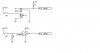
I think I can use the bottom circuit with a CMOS 4069 inverter to take the 12v input and generate a 5v ttl output. In this circuit the inverter input is pulled low to give me the high output to the PIC. When the switch is pressed the inverter input goes high (+12vdc) and causes the output to go low (<.5vdc) and pull the pic input to ground.

Looking at the data sheet I think I actually have to supply the cmos with 12vdc but this would then give a Vout High of 14.95 volts.

If I keep the CMOS with a 5vdc supply should I use a voltage divider on the input of the CMOS to get the voltage in the 0-5vdc range?

Or is there a better way of doing this? The relay coil adds noise, need a diode for emf and also has a limited mechanical life span, thus I am looking at a more robust solid state design.

Thanks
 

Attachments

  • CMOS 4069.JPG
    CMOS 4069.JPG
    31.3 KB · Views: 954
thanks for the quick reply

Please help me to understand the 22K resistor and inverting in software. I have been sketching it several ways but can't come up with what I think you mean.

Are you referring to the lower circuit and making the resistor there 22K? If so why would I then need to do any inverting in software (thus I don't think this is what you meant)

Are you referring to a new circuit (not shown) that would be a 22K in series from the switch to the pic? Then I would need a pull down resistor to keep the pin from floating.

I am missing something, please help :confused: It's been a long week here...
 

Attachments

  • 12vdc input 22k.jpg
    12vdc input 22k.jpg
    12.6 KB · Views: 368
Most PIC input pins are diode clamped to VDD, you must keep the current less than 20mA. yes a pulldown resistor would work, say 10K.
Here's one design used for RS232 signals.
**broken link removed**
 
Last edited:
So basically you can hook the pic pin to 12vdc as long as the current is limited to below the max input current on the data sheet (20ma). Then you are relying on the clamping circuit in the pic to take care of any voltage above vdd , right? Pretty simple, I like it.

Is this good practice? What if the input was for a 24vdc system instead of 12vdc? Use a 48K resistor?

what would be the absolute max voltage input? Or does in not matter as long as the current is controlled?

I'm using a 16f887 pic and it looks like the Port E 0, 1 & 2 inputs are indeed diode clamped to vdd.

If the switch is pressed the PIC should see 12VDC @ ~500uA. If, for whatever reason, someone connects the switch to 15vdc then the pic would see ~700uA, Correct? This is well under the 20ma max current for the inputs.

And lastly, if I were designing this to accept inputs ranging from 5vdc to 24vdc then I assume a more advanced circuit would be required to handle the variation? Maybe the voltage divider with a 5.1 zener diode

Thanks for your time and details...this is really helping me get some old brain cells wrapped back around electronics.
 
I would use an optocoupler in place of your relay.

Have a look at the 6N139 (single) or the HCPL2731 (dual).

creakndale
 
Last edited:
So basically you can hook the pic pin to 12vdc as long as the current is limited to below the max input current on the data sheet (20ma). Then you are relying on the clamping circuit in the pic to take care of any voltage above vdd , right? Pretty simple, I like it.

Is this good practice? What if the input was for a 24vdc system instead of 12vdc? Use a 48K resistor?
.

We used to put mains into a PIC through 390K resistors to meaure the main frequency !

Its the current you poke into the PIC that is the important thing.
 
Status
Not open for further replies.

Latest threads

New Articles From Microcontroller Tips

Back
Top