Huttojb1
Member
Hey all.
I have built a circuit which was orginal supported by you guys on here.
Here is the original link - https://www.electro-tech-online.com/threads/transistor-damage-needs-protection.149898/
But now i have connected all the circuits together and now I'm not getting the correct results as I expected.
I need to explain the circuit alittle so everyone can understand.
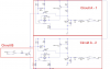
Ok Circuit B is the master switch on. This is switched on for a period of time (Activating NPN3). Whilst NPN3 is active Circuit A - 1 and Curcuit A - 2 is switched on from the PIC (Switching on NPN1 and NPN4) Now I can switch off NPN3 and both RL1 and RL2 are still energised.
Now comes to my issue, When switching off NPN1, RL1 should switch off and leave RL2 on, but it isn't. When switching off NPN4, RL2 should switch off, and leave on RL1 (or vice-a-versa)
There are going to be a few more Curcuit A - x (Probably about another 4). Can some one help me to isolate each circuit - it seems that the curcuits are effecting each other. When Each one is connected inderpendantly it works....
Hope this makes sense.....!!
Jason
I have built a circuit which was orginal supported by you guys on here.
Here is the original link - https://www.electro-tech-online.com/threads/transistor-damage-needs-protection.149898/
But now i have connected all the circuits together and now I'm not getting the correct results as I expected.
I need to explain the circuit alittle so everyone can understand.
Ok Circuit B is the master switch on. This is switched on for a period of time (Activating NPN3). Whilst NPN3 is active Circuit A - 1 and Curcuit A - 2 is switched on from the PIC (Switching on NPN1 and NPN4) Now I can switch off NPN3 and both RL1 and RL2 are still energised.
Now comes to my issue, When switching off NPN1, RL1 should switch off and leave RL2 on, but it isn't. When switching off NPN4, RL2 should switch off, and leave on RL1 (or vice-a-versa)
There are going to be a few more Curcuit A - x (Probably about another 4). Can some one help me to isolate each circuit - it seems that the curcuits are effecting each other. When Each one is connected inderpendantly it works....
Hope this makes sense.....!!
Jason