Electro Tech is an online community (with over 170,000 members) who enjoy talking about and building electronic circuits, projects and gadgets. To participate you need to register. Registration is free. Click here to register now.
Welcome to our site! Electro Tech is an online community (with over 170,000 members) who enjoy talking about and building electronic circuits, projects and gadgets. To participate you need to register. Registration is free. Click here to register now.
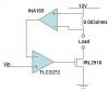
I agree with Pommie. The INA169 converts current through the 0.003 ohm resistor to a voltage that is referenced to GND. The INA169 needs a resistor from its output to GND. The datasheet tells how to select the value. This circuit will probably oscillate unless you add some frequency stabilization circuitry.
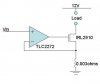
Below is a simpler way to do the same thing, if you don't need to have the source of the MOSFET grounded.
to me it looks like a diff amp looking at the voltage drop across a current shunt with a output that is a input to an amp thar has an adjustable ref in one input when the when the voltage drop across the shunt trips the second amp the transistor turns off removeing the load
joe
i'll take note, thankz for the advice. Its a microprocessor based light intensity controller. There will be a C8051F121 connect to a AD557 the to the Vin of TLC2272.
above is my reply to the topic If you look at the circuit as it is shown in the diagram then it wont be working as proportional controller If I assume for drawing sake the resistors and other elements are not shown then also there is one problrm with the circuit
When Voltage due to current (at negative terminal of opamp) is equal to Vin, which is the desired state, the output of opamp will be 0V which will switch off the load Don: when you want to make a feed back loop its better to feed the measured value which is the output of INA169 to the microprocessor and adjust the voltage supplied to the gate of MOSFET by the microporcessor
Since your load is a light (which has inductance) you can try for PWM control. (for which you will require just one Digital Output and Analog input port of your microprocessor)
The formula i derive out vin = Iout x R. And from what i heard from others, we are maintaining the output of TLC2272 to 0? So what the point of maintaing?
If I assume for drawing sake the resistors and other elements are not shown then also there is one problrm with the circuit
When Voltage due to current (at negative terminal of opamp) is equal to Vin, which is the desired state, the output of opamp will be 0V which will switch off the load.
Instruite, the op amp has extremely high gain (typically 175,000). In order to drive the MOSFET gate to, say, 5 volts, it would only need the noninverting input to be 29 microvolts greater than the inverting input (using Av=175,000). This is the principle behind all op amp negative feedback circuits. If we followed your reasoning, op amps would be worthless, except maybe as comparators.
Regarding the circuit, the IRL2910 is a poor match for the 3 milliohm resistor. It has Rds(on)=260 milliohms max. The INA169 has an input offset voltage of +/- 1mV max, so 10 amps (dropping 30mV) is about the miimum useable current if you want any accuracy. 10 amps will waste 2.6V across the IRL2910, and will cause it to dissipate 26 watts. The MOSFET needs to be "bigger" (lower ON resistance), or the sense resistor need to be a higher value. Which solution you choose depends on the maximum current desired.
It seems to me that implementing a current source with PWM, in a feedback loop, with a microcontroller in the loop, would require some serious programming to keep the loop from oscillating, but I must confess I've never tried it.
I think the circuit I posted above is the simplest solution.
Hi RON H
I know the difference in opamp and comparator and thats y in my explaination i clearly said it will be working as comparator and so I asked for the detail circuitary
Anyways I will just tell the point I was concerned with
The common mistake among student while implementing feedback loop with proportional control is that they forget when the desired state of error=0 is reached some bias is required to keep the system runing at desired point
Well this was in control system terminology
Let me put in simple words for the circuit
Like the feedback is at negative terminal
let suppose Vin is provided such that current should be 0.1A
Now if I assume that the circuit is well designed such that when current is say 0.2A the negative terminal voltage will be such that output of opamp will decrease till current becomes 0.1A
and when that happens the same negative termninal voltage which made current 0.1A should be maintained
The above circuit if properly designed will work for above condition
But now assume that the current is 0.08A now the above circuit will not work unless some negative voltage is provided at the negative terminal of the opamp
and doesnot seem to be the case in the above circuits
and reagrding the PWM control well I have implemented that for current controlled solenoid and it works fine
This site uses cookies to help personalise content, tailor your experience and to keep you logged in if you register.
By continuing to use this site, you are consenting to our use of cookies.