Continue to Site

Welcome to our site!

Electro Tech is an online community (with over 170,000 members) who enjoy talking about and building electronic circuits, projects and gadgets. To participate you need to register. Registration is free. Click here to register now.

  • Welcome to our site! Electro Tech is an online community (with over 170,000 members) who enjoy talking about and building electronic circuits, projects and gadgets. To participate you need to register. Registration is free. Click here to register now.

circuit to split combined DRL/turn signal into separate circuits

Status
Not open for further replies.

AMB_IV

New Member
Hello!
I'm driving a 2006 Cadillac SRX that I recently purchased. it's growing on me, but one thing that bugs me is Cadillac made the front amber turn signals do double duty as daytime running lamps (DRL). by double duty, there's only one circuit into the bulb and the flasher drives that circuit as either +12 V for DRL's, or alternating +12/0 V for turn signals (like normal). My goals:
1. I like amber turn signals but I'd really like white DRL's (like all the newer cars and the bright LED's)
2. North Carolina actually allows white turn signals but what fun is the trival solution?

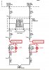
I've purchased replacement LED bulbs called switchbacks that have amber LED's on one circuit and white LED's on a 2nd circuit. but they don't work because the car doesnt' have two separate circuits. So to make those work I need to split the signal like this:
2006 Cadillac SRX flasher modes.JPG

schematically, it looks like this:
SRX front turn signal schematic markup.jpg


One point to bear in mind...the GM bulb socket wasn't fully populated ( 2 pins, 1 blank) but the aftermarket replacement parts are fully populated with three pins. so adding one more wire isn't impossible.

thanks for your time, I'm looking forward to your creative solutions!!
 

Attachments

  • SRX front turn signal schematic markup.jpg
    SRX front turn signal schematic markup.jpg
    70.4 KB · Views: 788
  • 2006 Cadillac SRX flasher modes.JPG
    2006 Cadillac SRX flasher modes.JPG
    76.6 KB · Views: 411
Hy AMB-IV,

Welcome to ETO. You are from the United States and you imply that you are in North Carolina - care to put that in your profile window that displays on the left and also put it on your profile page under 'Location'.

Interesting question. We like question like this where all the information is provided and is well presented.

My initial appraisal is that a circuit could be designed to meet your requirements. I will give this some further thought as will other ETO members no doubt.

spec

PS: Just wondering what a 2006 Caddy SRX looks like:


2016_07_03_Iss1_ETO_Cadillac_SRX_2006.jpg

 
Last edited:
It isn't possible to get a circuit to do exactly what you want, but something that comes close could be done.

In your diagram, where the input turns on after the 5th off period, there is no that the circuit can know that the turn signal has been cancelled. There is no difference in the input until the normal on period has elapsed and the input stays high. Similarly if the driver cancels the turn signal during the on period, there is no change that can be detected.

You could build a circuit that would energise the turn signal if the input had been low less than one on period ago. Otherwise it would power the DRL. Also, the lights would both be powered from the input so that the turn signals would flash and so that the DRLs would turn off when the car is turned off.

If that were instituted, the turn signals would flash once when the engine starts, then the DRLs would come on. When driver indicates a turn, the DRL would turn off, and the turn signal would flash. When the driver stopped indicating a turn, the turn signal would stay on for a moment longer than the on period of the flasher, then it would turn off to be replaced by the DRL.

If you made a delay circuit powering an automotive relay, that would work. Your delay needs to be just over the on period of the turn signal, and the relay would be change-over relay, so that NC (normally closed) powers the turn signal and NO (normally open) powers the DRL. The two sides would be independent, and the whole lot would be powered from the existing input.

When the input is on, after the short delay, the relay would be energised. That would turn off the turn signal and turn on the DRL, and the relay would stay energised.

When the driver indicates a turn, the input would turn off, so both lights would be off. The relay would be de-energised. During a flash of the turn signal, the relay would stay de-energised, and the time delay would not be reached before the flash finished. As long as the turn was being indicated, there would never be long enough for the relay to be energised, so during the on periods the turn signal would be on.

When the driver stops indicating, the input would stay on continually for long enough for the delay circuit to energise the relay, and the turn signal would be turned off and the DRL turned on.
 
Hy again AMB-IV

Here is an outline circuit to do your job. I haven't analyzed it in depth or optimized the components or the design, but all the same it should work.

The circuit may look complicated if you are not familiar with electronics but, in fact, it is quite simple and would be easy to build. As you are in the US the components, including a small case to house both left and right circuits and connectors, will be freely available and would probably cost around $15US.

If you favor this approach just say and I will post a practical circuit with defined PMOSFETs, optimization and with decoupling etc included.

You could have the drive white LED on even when the turn indicator lamp is flashing if required. This would necessitate a circuit modification.

By the way, we need to know what current each LED takes from the Cadillac SRX 12V supply line.

spec

2016_07_03_iss1_ETO_TURN_NORMAL_CONTROLLER_VER1.png
 
Last edited:
I think that circuit will need a amplifier. The voltage on C6 will fall slowly, and there will be a large range of voltages where Q7 and Q8 are both on.

The idea is correct.
A 555 wired as a re-triggered one-shot, where the timing period is longer than the turn-signal flasher period?
 
I think that circuit will need a amplifier. The voltage on C6 will fall slowly, and there will be a large range of voltages where Q7 and Q8 are both on.

The idea is correct.

Hy Driver

It is only an outline circuit as stated. I haven't bothered to work out the time constants or optimise- to busy watching the tennis on TV.:p

spec
 
Below is the LTspice simulation of my take on MikeML's 555 idea.
The 555 is configured as a re-triggerable one-shot with a period of about 1/2 second.
It thus reverts back to the running lights about 1/2 second after the turn signals stop. This time can be adjusted by changing R2 but the time must be longer than the ON time of the blinker.
V2 is the flasher/running light signal from the car.
M1 and M2 can be just about any N-MOSFET that can handle the LED currents.
R1 and R4 are likely included in the LED package and thus are not needed in the real circuit.
Note that the circuit is powered by the signal so doesn't require additional 12V power.
The main advantage of this over spec's circuit is that a 555 will have more stable timing (largely independent of voltage and temperature).

upload_2016-7-3_13-29-18.png
 

Attachments

  • 555 Run Light-Turn Signal Sw.asc
    2.9 KB · Views: 264
Last edited:
I think you will find that the amber and white LEDs are common cathode not common anode.
The -5V VBE reverse voltage of the 2N3906 transistor will be exceeded I suspect.
There are no gate stoppers, so the MOSFETs may oscillate.
There is no supply line HF decoupling.
The voltages on the pins of the 555 will exceeded the 555 substrate diode threshold at first turn-on.
The automobile 12V supply line is effectively connected directly to the 555 which means that hash etc on the 12V supply line is likely to blow the 555.
At first turn on there will be around 1.2A going through the 1N4148 diode which is unwise. A 1N400x rectifier diode would be much safer.
It is unwise to decouple the 555 control pin with a capacitor larger than 10nF.
Automobile grade components have not been specified so the circuit will not meet the environmental conditions for an automobile.

My circuit is intended to show the principle, and as I said has not been optimized.
The objective is to illustrate that the OP's function can be realized and also to establish if he would be happy building a circuit of that complexity.

The first objective has been achieved but the second has not- yet

spec
 
Last edited:
I think you will find that the amber and white LEDs are common cathode not common anode.
Good point. If so the output transistors need to be changed to P-MOSFETS.
The -5V VBE reverse voltage of the 2N3906 transistor will be exceeded I suspect.
Yes, I need to add a diode in series with the base.
There are no gate stoppers, so the MOSFETs may oscillate.
If they do oscillate it would only be momentarily during the turn on or turn off transitions and it wouldn't be visible.
There is no supply line HF decoupling.
I'll add a 0.1μF ceramic.
The voltages on the pins of the 555 will exceeded the 555 substrate diode threshold at first turn-on.
What threshold?? :confused:
The automobile 12V supply line is effectively connected directly to the 555 which means that hash etc on the 12V supply line is likely to blow the 555.
I think resistor R3 and capacitor C3 will take care of that.
At first turn on there will be around 1.2A going through the 1N4148 diode which is unwise. A 1N400x rectifier diode would be much safer.
Good point.
It is unwise to decouple the 555 control pin with a capacitor larger than 10nF.
I've never seen that limit in the data sheet but I'll change it to the 10nF shown in the example circuit.
Automobile grade components have not been specified so the circuit will not meet the environmental conditions for an automobile.
.....................
The circuit is mounted outside the engine compartment so likely the only extreme temperature beyond the 555's 0-70°C limit would be in cold weather, and I suspect it will still operate.
Even if it failed to trigger, one or the other of the lights would still blink so there's no safety hazard involved.

Below is the circuit with the above modifications, including P-MOSFETs to drive grounded LEDs with a common cathode.
Note that the MOSFETs should be standard type with a Vgs(th) of at least 2V.
Logic-level type MOSFETs may not fully turn off.

upload_2016-7-3_21-29-7.png
 

Attachments

  • 555 Run Light-Turn Signal High Side.asc
    3.2 KB · Views: 252
Last edited:
Below is the LTspice simulation of a somewhat simplified version of spec's circuit.
The time-constant R1C1 determines the delay until the running lights return after the turn signal stops. The delay needs to be slightly longer than the ON time of the turn signal.
C2 prevents short transient current glitches that appeared in the DRL LED when the turn signal was blinking.

upload_2016-7-3_22-31-28.png
 

Attachments

  • Turn-Running Lights Cont.asc
    2.1 KB · Views: 257
Last edited:
Thanks for your reply in post #10 crutschow.

I hope you didn't mind me mentioning.

Will respond to your points when I wake up properly.

spec
 
Below is the LTspice simulation of a somewhat simplified version of spec's circuit.
The time-constant R1C1 determines the delay until the running lights return after the turn signal stops. The delay needs to be slight longer than the ON time of the turn signal.
C2 prevents short transient current glitches that appeared in the DRL LED when the turn signal was blinking.

View attachment 100287
Clever implementation.:cool:

spec
 
Clever implementation.:cool:

spec
Thanks.
My goal when designing circuits is the quote attributed to Einstein: "Make things as simple as possible, but not simpler."
or KISS in the popular vernacular.
In this case I think your circuit approach fits that goal better than the 555 circuit.
 
Thanks.
My goal when designing circuits is the quote attributed to Einstein: "Make things as simple as possible, but not simpler."
or KISS in the popular vernacular.
In this case I think your circuit approach fits that goal better than the 555 circuit.
But the 555 circuit is more accurate. :p

spec
 
But the 555 circuit is more accurate. :p

spec
You're throwing my own words back at me. :rolleyes:
But I guess, in this application, it seems the added accuracy is not worth the added complexity (especially compared to the simplified circuit).
I mean, how much timing accuracy does the circuit really need? ;)
 
What threshold?? :confused: (substrate parasitic diode)

The 555 spec sheet is not very clear, definitive or comprehensive in some areas. It also makes some sweeping statements.

One parameter that is missing from the absolute maximum ratings is the maximum/minimum voltage on any pin with reference to the supply lines, so unless otherwise stated, you can only assume that the allowable over and under voltage is zero volts.

Generally the pins of a chip are isolated from the substrate by parasitic diodes. These diodes are fairly delicate and not designed to conduct current so they are easily damaged.

I've never seen that limit in the data sheet. (10nF limit on control pin decoupling)
No, I can't find it on data sheets either, but at one time there was a limit of 10nF to limit the surge current at turn-on through the top resistor of the three internal voltage divider resistors. Maybe the resistors have been beefed up on modern 555s. :)

The circuit is mounted outside the engine compartment so likely the only extreme temperature beyond the 555's 0-70°C limit would be in cold weather, and I suspect it will still operate.
I had envisioned the unit being mounted near to the lights so that the existing signal wire simply plugged into the unit and two short wires connected to the light unit. An earth wire would also be required.

I had thought of either one unit with both left and right controllers in one case, or more convenient two separate units.

Incidentally, it may be necessary to put a resistor in parallel with each LED to make them take the same current as filament lamps if the automobile electronics uses current sensing to detect a blown lamp. Of course, this assumes that the original lamp was a filament type.

Even if it failed to trigger, one or the other of the lights would still blink so there's no safety hazard involved.
This is true in essence, but taking the point to the extreme the 555 may go short circuit, under high temperature for example.

Below is the circuit with the above modifications, including P-MOSFETs to drive grounded LEDs with a common cathode. Note that the MOSFETs should be standard type with a Vgs(th) of at least 2V.
Logic-level type MOSFETs may not fully turn off.

Good observation- that is a fundamental requirement for the circuit as I saw it. This is ironic because normally in a design you are scratching around trying to find a MOSFET, especially PTYPE, than can be turned on with a low voltage.:eek:

spec
 
Last edited:
Wow!
Thanks for all the responses I really appreciate the enthusiasm everyone has for this question.
I owe y'all current measurements on the LEDs. I hope to get that later today or maybe tomorrow evening. It's a bit more difficult than you might imagine. The procedure to get to the lamp is:
  1. Remove the front wheel
  2. Remove the inner fender liner
  3. Unscrew the six fasteners on the lamp cover
  4. Pull off cover and twist socket to remove from lamp
Right now the rears are up on stands so I can replace a clunky bushing. I'll work on the current measurements after I get the rear end back on the ground.

I'll probably make a parts list next so I can order parts and breadboard the solutions.

Incidentally, it may be necessary to put a resistor in parallel with each LED to make them take the same current as filament lamps if the automobile electronics uses current sensing to detect a blown lamp. Of course, this assumes that the original lamp was a filament type.

You are exactly right. If supplemental resistance isn't added the turn signal indicators on the IP will "hyperflash" indicating bulb failure AND the LED itself will not be driven to flashing. My first step was making the flasher modification given in this post: https://www.cadillacforums.com/forums/forum.php#/forumsite/20562/topics/741369?page=1
With led on one side and filament bulb on the other, and hazard lamps activated it was flashing about 1.4 hz (estimates, 17 flashes in a 12 second video). I didn't think to make an unmodified baseline video for reference. Both sides were fast; the bulb didn't quite go dark in between flashes, but the LED had very clear cutoff in between on cycles. I'll post the video if there's interest.

Also the LED flashed even faster when in turn signal mode only.
I took a quick look at the relevant FMVSS regulation, I don't remember it having a clearly stated flash rate. It seems to be practice to flash the lamps at one to two Hz.

I may repair the flasher back to the original resistances and work the required resistance into this circuit.

Again I really appreciate everyone's contributions
Mac
 
Last edited:
.......................
One parameter that is missing from the absolute maximum ratings is the maximum/minimum voltage on any pin with reference to the supply lines, so unless otherwise stated, you can only assume that the allowable over and under voltage is zero volts.

Generally the pins of a chip are isolated from the substrate by parasitic diodes. These diodes are fairly delicate and not designed to conduct current so they are easily damaged.
...........................
I fully understand that.
I just didn't see where that would occur in the circuit I posted. :confused:
This is true in essence, but taking the point to the extreme the 555 may go short circuit, under high temperature for example.
I don't think the circuit will exceed the 555 limit of 70°C (158°F) where it's located at the front of the car (unless it's parked facing the sun on a summer day in Death Valley). ;)
 
I fully understand that.
I just didn't see where that would occur in the circuit I posted. :confused:
...

I concur. I cannot see that the Trig (or any other) input to the 555 swings above Vcc, or below Gnd.
 
Status
Not open for further replies.

Latest threads

New Articles From Microcontroller Tips

Back
Top