Continue to Site

Welcome to our site!

Electro Tech is an online community (with over 170,000 members) who enjoy talking about and building electronic circuits, projects and gadgets. To participate you need to register. Registration is free. Click here to register now.

  • Welcome to our site! Electro Tech is an online community (with over 170,000 members) who enjoy talking about and building electronic circuits, projects and gadgets. To participate you need to register. Registration is free. Click here to register now.

Circuit to beep every time light is sensed?

Status
Not open for further replies.

airman86

New Member
I'm making a project for one of my mechanical engineering classes where I have to design and recreate a theoretical problem in the book. The one I am building involves a rotating mass, and some cables. The question is to find the tension in a certain cable with a mass attached at a certain RPM.

I plan on using a circular disc attached to the rotating shaft with a small slit on the edge. On one side of the disc, a photo diode under the hole, and a light source on top. So - every time the mechanism completes one full rotation, the photo diode "sees" the light through the hole on the disc and beeps. The beeps would be counted over a certain period of time to calculate rotations per second. I'd like to build a circuit to accomplish this. I work at radioshack and I can get all the parts I need, I just don't kow which ones.

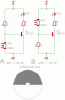
This is the one online, I could hook it to a beeper/buzzer:
Photo relay circuit | www.circuitstoday.com

I have tried this, and substituted a 2N3904 (we don't have BC resistors, the 3904 is comparable - just rotated 180 degrees, correct?). Following the schematic exactly, I had no luck. I tried several different transistor possibilities and nothing has worked. The transistor stays 'open' all of the time, even with a tiny amount of current flowing to the base. Adjusting the pot from wide open to the full 10k didn't make a difference.

I really hope to find some expertise here. I searched a little bit but I coudn't really narrow down what I wanted. Most results weren't very relevant. If possible, I'd rather not use transistors, I kind of would like to use ICs instead of transistors - because that is what I want to learn about.

A really slick thing that would be cool and earn a few extra points would be to have an LCD display instead with one or two decimal places indicating the RPM. Is this possible? I am very amateur at this and don't have much knowledge with LCDs/ICs/etc. We carry LCD displays here, one digit at a time. The displays we have are these:

7-Segment LED Digital Display - RadioShack.com

Thanks for the help.
 
Yes it's possible to use an LCD to display the RPM.

If you use a microcontroller all the counting can be done in software.
 
This piece is really just optional and is just out there to add some flare. It's not imperitve to have it, so I'm not going to put too much work into it (i.e. progamming ICs and stuff...that's just a little too much work if that's what needs to be done).

So - I guess i'm going to scrap the LCD display and go back to doing the beeps.

Why wouldn't my circuit have worked in the schematic I posted?
 
The circuit you posted will work.

You can simplify it further by removing the relay and replacing it with a piezo beeper. The relay is only needed for large loads or controlling mains appliances.
 
The circuit you posted will work.

You can simplify it further by removing the relay and replacing it with a piezo beeper. The relay is only needed for large loads or controlling mains appliances.

Yeah. I tried this but I still couldn't get it to work. Like i stated in the OP, the transistor never realy "closed" even with the photo resistor in complete darkness and the pot turned all the way to 10k. The only way my voltmeter would ever read OPEN was if the base was completely disconnected from any current. I thought the whole point of transistors is that it takes a certain AMOUNT of current to cause the emmiter/collector to conduct through? I.e, the package that my 2N3904 came in says that it takes 200mA to open.

Maybe my misunderstanding is wrong, bear with me :)

NOTE* The circuit diagram I posted is for a setup to beep when it is dark. What's the correct way to reverse this? I tried using a SPDT relay and reversed the way it was intended to work with the SPST relay it called for. Either way, I couldn't get the relay to engage in any way. I can look at the circuit and I understand exactly what is going on, but I can't get it to work.
 
Last edited:
The circuit contains a photo diode, not a photo resistor.
 
The circuit contains a photo diode, not a photo resistor.

Oh, good call. I have a bunch of photo resistors and the only photo diodes we have here are infrared. I could use infrared light, but I like the "cool" factor of a colored LED that uses visible light :)

Is there a comparable way to do this with a photo resistor? If not, I'll attempt it with the photodiode. In the schematic, which one is the emitter and the collector?
 
Last edited:
Transistors are not "open" or "closed". Doors and windows are open or closed.
Transistors are turned on or are turned off.

The photo-diode has a current that is much too low to turn off the transistor. A photo-transistor has about 100 times the current of a photo-diode and would work.

A photo-resistor will work if the light is very bright and the slotted shaft turns very slowly.
 
A photo-resistor will work if the light is very bright and the slotted shaft turns very slowly.

the mechanism wil be turning a few rotations per second. I don't think that would be slow enough.

This acceptable to use?

Matched Infrared Emitter and Phototransistor Detector - RadioShack.com

Looking at the reviews, apparently the guy at the top accomplished what I am trying to do...

https://www.radioshack.com/product/...productId=2049723&tab=custRatings#showReviews
 
Last edited:
You should buy prime parts from a real electronic parts distributor made by a well known manufacturer (not no-name seconds) that have a detailed datasheet (not just the size and the temperature range). Then the parts will work properly and will meet their spec's.

A photo-resistor is very slow to respond.
A photo-transistor like this one is much faster.
A photo-diode is very fast but needs an amplifier.
 
When you say 'open' does that mean the transistor is an 'open valve', passing current? Or by 'open' you mean it is an open circuit which blocks current? Or maybe it's both (but not at the same time).

If it's not powered by a 9V square battery, there is a serious design problem with R1, if set to minimum resistance, the transistor will be destroyed and will behave like a stuck-closed relay contact. (in practice, a square 9V battery often doesn't have enough power to damage most transistors). If the light source isn't bright enough, the transistor also won't switch off.

audioguru, what is the ms. response-time of a photo-resistor? Maybe it's fast enough for this app.?

Alternatively, if the light was bright enough, the present transistor could instead be a photo-transistor, it would then sound a beep while illuminated. The 10K pot and photodiode can of course be discarded.
 
Last edited:
Hi airman,

you might try the circuit modified for an LDR. Basically you can use any LDR.

The example is calculated for the commonly used LDR03, which has a resistance of about 1KΩ when exposed to bright light and 5 - 13MΩ in the dark.


The dark resistance changes as follows: 1 sec/100KΩ, 5 sec/300KΩ.
ton=50ms, toff=35ms

The LDR05 is slighter faster (ton=35ms, toff=25ms) and has a higher dark resistance of 11 -40MΩ.

Making the photo interruptor with an acrylic glass disk, one half painted black, will result in equal dark and light time, giving the LDR more time to react. (change resistance)

Attached are two example circuits which you might select according to your desire.

Motor rpm recognition should be possible up to 700rpm.

The transistor symbol means: base=vertical bar, emitter=arrowed slanted pin, collecor slanted pin.

Boncuk
 

Attachments

  • LDR.gif
    LDR.gif
    6.2 KB · Views: 623
Last edited:
That depends on the power demand of the buzzer. LDRs can stand max 90mW (Vmax=150V).

If the on resistance gets low enough it should work.

Never tried though.
 
Good suggestion.

Yes, you can get piezo buzzers which only require 5mA, even even the CdS cell has a light resistance of 100R the voltage drop will only be 0.5V.
 
Status
Not open for further replies.

Latest threads

New Articles From Microcontroller Tips

Back
Top