Continue to Site

Welcome to our site!

Electro Tech is an online community (with over 170,000 members) who enjoy talking about and building electronic circuits, projects and gadgets. To participate you need to register. Registration is free. Click here to register now.

  • Welcome to our site! Electro Tech is an online community (with over 170,000 members) who enjoy talking about and building electronic circuits, projects and gadgets. To participate you need to register. Registration is free. Click here to register now.

circuit from 1991, still best way to go?

Status
Not open for further replies.

motolectric

New Member
Hi,

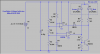
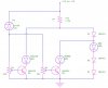
I found this circuit for a 3 LED voltage indicator that is pretty much what I need. But since it is from 1991 I wanted to know if it is still the best way to show the voltages or if perhaps there is a chip or something that will do it better/easier.

The goal is to have a small indicator that

lights just the Red LED if the voltage is below about 12.5 volts,
the Green LED begins to light at about 12.5 and the Red LED fades,
at about 14.25 the Yellow LED begins to come on and
by 14.75 the Green LED has faded out.

I like the simplicity of this circuit and that it could be housed in a very small case that I have found.

But any and all advice is appreciated.

Thanks,

M./
 

Attachments

  • va.circuit.only.jpg
    va.circuit.only.jpg
    45.6 KB · Views: 245
Aside from being a little bit temperature dependent, it's a clever circuit. One caution; you should be certain that the potentiometers are never at their 'max' positions. If they are, you will toast the zener diode and the associated transistor.
 
My answer would be that if it worked in 1991 it should work just fine now :)
In all seriousness, where is the fun in doing it with an IC? ICs are fine for large, complex devices with multiple functions and I/Os, where saving space and cost is an important consideration...but for a little DIY project like this, discrete components are a lot more fun to put together.
 
Aside from being a little bit temperature dependent, it's a clever circuit. One caution; you should be certain that the potentiometers are never at their 'max' positions. If they are, you will toast the zener diode and the associated transistor.

That could be easily solved with a small series resistance I would imagine.
 
I think the circuit is not the best way to go.

The setpoints for yellow and green depend on each other too much and therefor the circuit is difficult to adjust.

You'd better off using a window comparator.

Boncuk
 
Thanks and more questions

I want to thank everyone who has given me feedback on this circuit. And now of course I have a few more questions.

That could be easily solved with a small series resistance I would imagine.

A note on the site where I found the schematic stated

Important: to simplify the circuit and improve
the performance, no protection was added to d4.
You must set r2 & r3 to ground before starting!
If they are adjusted to the d4 side, parts will smoke!

How would I ensure that the above release of the magic smoke could not happen?

My answer would be that if it worked in 1991 it should work just fine now :)
In all seriousness, where is the fun in doing it with an IC? ICs are fine for large, complex devices with multiple functions and I/Os, where saving space and cost is an important consideration...but for a little DIY project like this, discrete components are a lot more fun to put together.

Well, I am researching this as a possible circuit to offer to motorcycle owners. Big twin cylinder motorcycles have a hard time starting due to many reasons but one of them is that the riders park the bikes with the batteries half depleted. Then when they try and restart it overtaxes the batteries leading to premature battery failure. Many riders eat a battery a year which contributes tremendously to the safe disposal problem of lead acid batteries.

So the goal here is to produce a simple to understand easy to mount indicator that will help the riders extend the life of the batteries.

And that means cost effectiveness is important along with small size.

I think the circuit is not the best way to go.

The setpoints for yellow and green depend on each other too much and therefor the circuit is difficult to adjust.

You'd better off using a window comparator.

Boncuk

Is there a circuit online anywhere that will accomplish the same function as this circuit that uses a more accurate or easier to adjust/maintain topology? One that uses the mentioned window comparator or something equally as accurate?

One of the main appeals to me of this circuit is that is shows multiple states using only 3 LEDs.


Again, thanks for all the feedback and advice.

M./
 
To protect the transistors and zener, put 100 ohms in series with the base of each transistor.
 
Here's a slightly simpler circuit without the zener damage problem:
**broken link removed**

This battery monitor circuit uses 3 separate LEDs.
The red LED turns on from 6v to below 11v.
It turns off above 11v and
The orange LED illuminates between 11v and 13v.
It turns off above 13v and
The green LED illuminates above 13v
 
Last edited:
Another way to go. Something I did back in 1998 to tell me if my airplane alternator is charging. Has three states with one Bi-color common-anode LED; Amber if low, Green if good, Red if too high.

You can tailor the trip points by playing with R1, R2, and R3.

Today, I would probably redo it using an LM431 for the voltage reference in place of the Zener.
 

Attachments

  • OverUnder1.png
    OverUnder1.png
    24.3 KB · Views: 162
  • OverUnder2.png
    OverUnder2.png
    14.6 KB · Views: 135
Last edited:
To protect the transistors and zener, put 100 ohms in series with the base of each transistor.

Thanks very much, I'll look into that.

Another way to go. Something I did back in 1998 to tell me if my airplane alternator is charging. Has three states with one Bi-color common-anode LED; Amber if low, Green if good, Red if too high.

You can tailor the trip points by playing with R1, R2, and R3.

Today, I would probably redo it using an LM431 for the voltage reference in place of the Zener.

Well I need the be able to make sure it is very clear to the rider when his battery is anywhere between 12.5 and 12.2 volts as that is often the area where they are when they get parked. Then over a week or 2 modern electronics have sucked them down another .2-.4 volts and that where they are when they next start. Then batteries get hosed due to being in a somewhat depleted state and the high current draw (like 52-55 amps for 1-2-3-4 seconds) required to start a large discplacement twin cylinder motorcycle.

So a window of 11-13 is too wide. And when a voltage regulator goes south they often overcharge the batteries for a while before they start blowing fuses and during that time the battery is being damaged, so I need to show the overcharge state also up around 14.5 V or more.

I appreciate the new ideas. But I think I will try this circuit out with the added resistors and I also need to add a relay so it will only get voltage when the bike is turned on.

Does anyone see any issues with adding a micro board sized relay?

If I don't add it then the circuit/LEDs will also slowly pull down the battery. Although I keep my bike on a float charger in the garage many motorcyclists are urban dwellers and have to keep their bikes parked on the street or where they can't get AC to a charger.

Thanks, Happy New Year.


M./
 
Status
Not open for further replies.

Latest threads

New Articles From Microcontroller Tips

Back
Top