Continue to Site

Welcome to our site!

Electro Tech is an online community (with over 170,000 members) who enjoy talking about and building electronic circuits, projects and gadgets. To participate you need to register. Registration is free. Click here to register now.

  • Welcome to our site! Electro Tech is an online community (with over 170,000 members) who enjoy talking about and building electronic circuits, projects and gadgets. To participate you need to register. Registration is free. Click here to register now.

Chopped AC to ignition coil - Some questions

Status
Not open for further replies.

J_Nichols

Member
Hello, I have seen some time ago a youtube video that I want to replicate.

The idea is to to input the main walls into car's ignition coil. Of course, I want to make it taking precautions.
The circuit uses a dimmer to chop the AC and also a capacitor to regulate how much current flows into the ignition coil.

The first thing I want to know is what kind of device is this:
15e90db72afaf5c8dfbfd3fa2abc0805.png

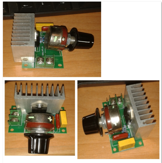
https://gyazo.com/15e90db72afaf5c8dfbfd3fa2abc0805

I thinkt it's a dimmer, but I'm not sure. That is the device I have, not from the video.
 
If 'sparks' are the desired output from the coil, a dimmer doesn't work very well(or if at all). An ignition coil, to make a spark needs a sudden stop of voltage to make the spark. A square wave not a chopped sine wave like a dimmer gives. Dimmers work well on resistive loads, like a light bulb. Not so good on inductive load like an ignition coil.
 
If 'sparks' are the desired output from the coil, a dimmer doesn't work very well(or if at all). An ignition coil, to make a spark needs a sudden stop of voltage to make the spark. A square wave not a chopped sine wave like a dimmer gives. Dimmers work well on resistive loads, like a light bulb. Not so good on inductive load like an ignition coil.
This is the circuit I want to replicate:
I didn't find the video before.

Of course, I agree with you that square wave DC is the best. I have already tested with PDC. I want now to test with AC.
 
Using a light dimmer to energize an ignition coil often attracts the reaction that it will not work, but clearly it does and I wondered why.

I suspect the answer is that a light dimmer does generate a fast high voltage waveform if the SCR triggers near the AC signal peak. This generates an input signal akin to a capacitor discharge ignition (CDI), rather than the stored energy principle of a traditional Kettering ignition system.

spec
Thank you for the explanation.

But one question before we keep on the conversation...
The photos I posted in the first post of this thread... Is it a light dimmer?
 
Bear in mind car ignition coils are usually autowound, so the o/p would not only be 1000's of volts but referenced to the mains, extremely dangerous.
 
Thank you for the explanation.

But one question before we keep on the conversation...
The photos I posted in the first post of this thread... Is it a light dimmer?
Can you read the part number off the black plastic case?

spec
 
But one question before we keep on the conversation...
The photos I posted in the first post of this thread... Is it a light dimmer?

It looks like it could be a dimmer but less any part number data it is really hard to say for sure. As to using a dimmer with an automotive ignition coil? Did it many times with the old style automotive ignition coils and running off 120 VAC 60 Hz US mains it worked fine. A slick trick is to find a clear glass large light bulb. Using aluminum foil shape a cap (dome) for the bulb. Ground the bse of the bulb and connect the HV to the aluminum foil. In a dark room you get a pretty cool lightening show in the bulb.

As is the case there are dangerous high voltages present from mains voltage to the coil output. Apply normal safety precautions.

Ron
It does look like a dimmer- the small component could be a diac. But there there are only two connections and you would expect three: live input, switched output, and neutral.

spec
 
It does look like a dimmer- the small component could be a diac. But there there are only two connections and you would expect three: live input, switched output, and neutral.

spec

Yeah, I was seeing the resistor, the cap and was in search of an elusive diac. :)

At just about any home improvement store basic 450 to 600 watt incandescent lamp dimmers average $4 to $9 USD. Most dimmers around here (in the US) only have two terminals. Here is an example if you click on the 360 rotation arrow you will see what I mean. They use a Hot and Load terminal and that is all.

Ron
Hmm- that makes sense. I have just looked at a UK light dimmer and it is as you say- just two connections, live in and live switched out.

I can imagine a dimmer circuit that would work with just two wires providing the load were resistive and returned to neutral when not powered, but there would be problems with a reactive load or a battery, I think. Is there an example of a two-wire dimmer schematic anywhere?

spec
 
Last edited:
Hmm- that makes sense. I have just looked at a UK light dimmer and it is as you say- just two connections, live in and live switched out.

I can imagine a dimmer circuit that would work with just two wires providing the load were resistive and returned to neutral when not powered, but there would be problems with a reactive load or a battery, I think. Is there an example of a two-wire dimmer anywhere?

spec

Now that you mention it, I never really gave it much thought. So now, here I sit looking at images of very basic lamp dimmers and my head hurts, trying to envision the dimmer in circuit. :) Oh well, tomorrow is another day.

Ron
 
This is for reference only do not build it.
**broken link removed**
 
It looks like it could be a dimmer but less any part number data it is really hard to say for sure. As to using a dimmer with an automotive ignition coil? Did it many times with the old style automotive ignition coils and running off 120 VAC 60 Hz US mains it worked fine. A slick trick is to find a clear glass large light bulb. Using aluminum foil shape a cap (dome) for the bulb. Ground the bse of the bulb and connect the HV to the aluminum foil. In a dark room you get a pretty cool lightening show in the bulb.

As is the case there are dangerous high voltages present from mains voltage to the coil output. Apply normal safety precautions.

Ron
It would be better to use a step down transformer and input 12 VAC into the car ignition coil?
I have at home a step down transformer. I think it will be much safer.

The rest of the circuit would be the same... but instead of using 220 VAC I would use 12 VAC.
 
1000's of volts is still dangerous, however not being directly connected to the mains is an improvement.
I personally have had clouts from a ignition coil operating from a 12v system, its not very pleasant but I survived.
A sine wave wouldnt quite give the same results as the waveform the coil was designed for, maybe a little less but thats not a bad thing.
 
It would be better to use a step down transformer and input 12 VAC into the car ignition coil?
I have at home a step down transformer. I think it will be much safer.

The rest of the circuit would be the same... but instead of using 220 VAC I would use 12 VAC.
I agree but one consideration is you need a square or rectangular waveform when using an automotive ignition coil. A simple transformer (step down) stepping down 120 VAC or 220 VAC with a 60 or 50 Hz sine wave won't work. Thinking about automotive ignition years ago, before electronics. When ignition points were used the spark was on the break. You needed the magnetic field to collapse instantly. Could a;lso be done using a reluctor ring but a simple step down with a sine wave out won't work. Worth a try but I never got the step down to work with the old coild of the 50s and 60s.

Ron
 
As I understand it ignition coils operate a bit like a flyback trans in an smps, there is a step up in turns ratio, however not as much as you'd think.
The primary when the points open 'flies back' giving a reversed increase in voltage, a popular points gap in the 70s was around 20 thou with a secondary voltage of 20kv, at 20 thou the primary flyback voltage would have been around a few hundred volts, otherwise flashover would happen.
Call it 200v, to get 20kv the turns ratio would have been around 100.
Connecting a coil to 12v ac would then give an output of very approx 1.2Kv.
It depends what the O/P wants, this may not be enough, in which case Ron you are right and I stand corrected.

So you could convert the 12v ac to dc and use a ignition coil driver, there are some nasty ones on the web that dont protect the switching transistor from spikes, heres some ideas:
https://www.rmcybernetics.com/projects/DIY_Devices/homemade_ignition_coil_driver.htm
 
Hmm, driving two coils in antiphase, as in the second configuration in your link, is a clever idea.:cool:

spec

PS: to dive a coil in either mode, Kettering or capacitor discharge (CD), you need a switching device with around 600V rating.
 
Status
Not open for further replies.

Latest threads

New Articles From Microcontroller Tips

Back
Top