Continue to Site

Welcome to our site!

Electro Tech is an online community (with over 170,000 members) who enjoy talking about and building electronic circuits, projects and gadgets. To participate you need to register. Registration is free. Click here to register now.

  • Welcome to our site! Electro Tech is an online community (with over 170,000 members) who enjoy talking about and building electronic circuits, projects and gadgets. To participate you need to register. Registration is free. Click here to register now.

Choosing Capacitor Value For My Tesla Coil

Status
Not open for further replies.

Fluffyboii

Active Member
Hi,
I am working on a tesla coil and this is the most pricy and time consuming project of my life. I discovered how hard to build a resonating transformer in a hard way.
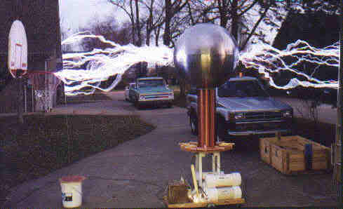
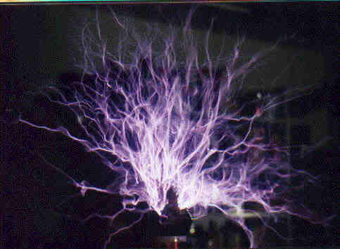
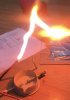
Actually I am kinda happy with my setup. I got more then 10 cm sparks. But thats not enough.

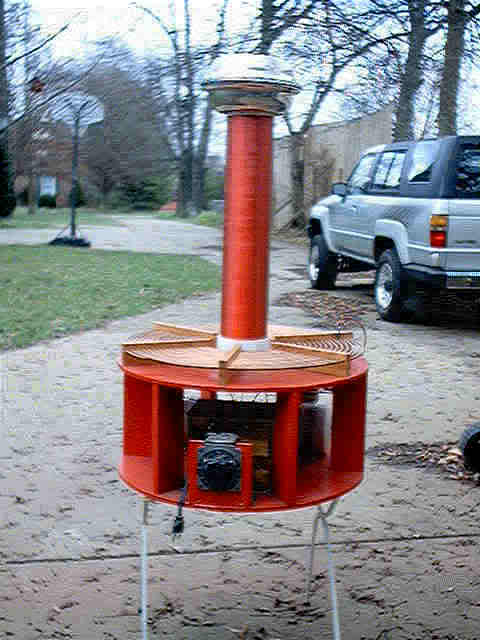
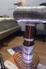
Secondary: 910 turns, diameter 7cm, length 47cm. 24awg 200 meters wire used.
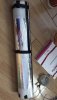
Primary made from 4 meters of fridge pipe 6 turns ideal resonance for now

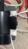
I made a huge foil capacitor after exploding different homemade ones. The single capacitor is 16 nano farads. Before I roll it It was 1 nano farads but It increased alot (I knew It will increase but not that much)
I use a flyback with a ZVS driver and a modified M.O.T. It consumes 3.5 Amps at 10 volts But I can't measure it with 55 volts because its to much for my multimeter.
Spark gap can be widen at 3 cm when working with 55 volts but at 30 volts max length is 2cm.
My flyback primary wires are thin because of the spacing problem and wire gets over 90 degrees if I use it at 55 volts for too long. I tried to put flyback in oil but it leaked so I give up.
The problem is I saw people geting way better results with lower voltage at ZVS drivers and less power. And everyone seems like using at least 10 turns on primary. And I don't have a proper ground connection in my house. I got long sparks jumping to primary coil from my secondary. I put a pipe around the secondary to prevent that But because the lack of a ground connection it some how happens. I tryed to lower the primary for better coupling but that didn't help too.
I wonder If I lower the capacitor value and increase the turn number to achive resonance, can that increase performance by increasing the magnetic flux. Or It will be the same. The 16nf capacitor is my only working capacitor and I don't want to cut it for lowering the capacitance and probably my flyback isn't able to charge that fully until the spark gap fires. But the copper tubing isn't cheap :/
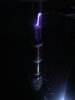
It feels like I am doing something wrong. You can see my early test picture, The new output is better than that. I don't have to much photos But I can take more if needed. I didn't find any usefull information on my mother language :(

Sorry for bad English. I am writing on a phone and because of that I can't check for spelling or grammar mistakes. I hope this will not melt your eyes.
 

Attachments

  • E8E43B43-A8DB-43CE-B4D8-52BE354D2EE3.jpeg
    E8E43B43-A8DB-43CE-B4D8-52BE354D2EE3.jpeg
    976.6 KB · Views: 316
  • CFA8CF81-7C8A-4A10-BF62-5FD9FFBEFBBD.jpeg
    CFA8CF81-7C8A-4A10-BF62-5FD9FFBEFBBD.jpeg
    1.2 MB · Views: 280
  • 12197862-FBC7-44A7-BCD3-4C7130FEB1D3.jpeg
    12197862-FBC7-44A7-BCD3-4C7130FEB1D3.jpeg
    115.5 KB · Views: 285
  • 9B748727-9433-4F99-9BF1-0FDBFCFD5CD1.jpeg
    9B748727-9433-4F99-9BF1-0FDBFCFD5CD1.jpeg
    173.9 KB · Views: 361
  • FCA47582-C3F8-47F5-904C-9373DE56ACED.jpeg
    FCA47582-C3F8-47F5-904C-9373DE56ACED.jpeg
    181.6 KB · Views: 292
  • CF5EEC52-ADFF-4FCF-9C6A-939CFA67F577.png
    CF5EEC52-ADFF-4FCF-9C6A-939CFA67F577.png
    287.8 KB · Views: 289
you need to measure the secondary inductance and the distributed capacitance of the secondsry. measuring the secondary inductance is pretty straightforward, but the capacitance might not be. if you have built your coil standing on top of a piece of sheet metal, you would disconnect the bottom of the secondary from the sheet metal and measure the capacitance between the sheet metal and the secondary. because of the inductance of the secondary, the capacitance might end up on the low side. an indirect method of measuring the capacitance would be to use a signal generator and oscilloscope. connect the signal generator to the bottom of the secondary with the sig gen ground going to the sheet metal. sweep the sig gen until you find resonance. this will be a dip in the response because the secondary circuit is series resonant. this measurement should be done with the corona cap and primary coil in place. after the measurement reconnect the bottom of the secondary to the sheet metal. you can then determine the capacitance using the known inductance and frequency (actually since the resonant frequency has now been measured, you really don't need to know the capacitance, but the capacitance is still useful to calculate). the resonant frequency, now that it's a known quantity will help you determine the values for the primary inductance and the capacitance required to resonate the primary. to simplify the math, you can measure the primary inductance, and look up on [this chart] to find where the primary inductance meets the line for the secondary's resonant frequency. this will give you the value needed for the primary capacitor.
 
you need to measure the secondary inductance and the distributed capacitance of the secondsry. measuring the secondary inductance is pretty straightforward, but the capacitance might not be. if you have built your coil standing on top of a piece of sheet metal, you would disconnect the bottom of the secondary from the sheet metal and measure the capacitance between the sheet metal and the secondary. because of the inductance of the secondary, the capacitance might end up on the low side. an indirect method of measuring the capacitance would be to use a signal generator and oscilloscope. connect the signal generator to the bottom of the secondary with the sig gen ground going to the sheet metal. sweep the sig gen until you find resonance. this will be a dip in the response because the secondary circuit is series resonant. this measurement should be done with the corona cap and primary coil in place. after the measurement reconnect the bottom of the secondary to the sheet metal. you can then determine the capacitance using the known inductance and frequency (actually since the resonant frequency has now been measured, you really don't need to know the capacitance, but the capacitance is still useful to calculate). the resonant frequency, now that it's a known quantity will help you determine the values for the primary inductance and the capacitance required to resonate the primary. to simplify the math, you can measure the primary inductance, and look up on [this chart] to find where the primary inductance meets the line for the secondary's resonant frequency. this will give you the value needed for the primary capacitor.
Hi, I changed the thin wire around the flyback to a thicker one and that increased the power output alot. After using it for 5 seconds one mosfet got overheated and died. Now I am using my backup ZVS driver with lower voltage components (Its not modified for high voltages). Flyback is working fine but Its not charging my capacitor now. Instead of producing sparks its makes a strait line (like there is not a capacitor). So I derolled my foil capacitor and check for damage. But capacitor was just fine. I am confused right now, I might broke my flyback again. And I changed the shape of my primary coil to a flat one. But thats made the performance worse. But It stoped arcing to secondary to primary. My seconday coil has some black dots on it because of the sparks hits from the primary.
Now my tesla coil isn't functioning and thats annoys me alot.
 
We all have to start some where it is a learning process. I started out small profected each TC = Tesla Coil then build a larger TC. Each TC was bigger and better. I could never get big powerful arcs & sparks from a flyback they are good for small desk top TCs. I learned that 950 turns on the secondary is a happy number that all TCs like. 18 turns on the seconds works good with the primary it will usually tap about 16 or 17 in that range. I built .1uf rolled capacitors for a while then started buying caps to make MMC capacitor banks. Capacitors need to be over rated 2 times power supply voltage for it to be almost bullet proof. I tried all sizes and shape primary coils, flat would with 1/4" between the 1/4" copper tubing works best with a 14K volt neon with 18 turn primary tapped at 16 that is about 875 volts per turn. Keep inside diameter of the primary coil 2.5" away from secondary coil to prevent arcs. When you wing a secondary coil on PVC pipe do it in summer in hot weather on inside the house then paint it with 2 coats of polyurethane varnish. If you wind a 950 turn coil in cold weather when temperature warms up wire expands then coil slides off the PVC pipe. Your capacitors and spark gap are the key to long arcs & sparks. Capacitors with a high power loss takes away from the secondary coil output. Don't waste time building a rotary spark gap, a vacuum fan spark gap works much better and is easy to build using the motor from an old junk vacuum cleaner and variac speed control. Use the variac to dial in the spark length you want. My first good TC was 4" pvc pipe with 1 neon transformer output was about 14" later better capacitors made 20" sparks. 2 neons in parallel did about 30" sparks and 3 neons in parallel die about 40" sparks. Then I built TCs with 6" pvc pipe with 3 to 6 neons in parallel output arcs were up to 6 feet. Next I built a TC with 10" pvc pipe output was 12 ft sparks. In the back yard using a top load 3 ft diameter and 12 ft sparks it produces a 27 ft diameter circle of arcs. I have not been on the Tesla Coil forum in several years it is much more active than this forum. As your secondary pvc pipe gets larger wire size needs to get larger also to keep the length to diameter ratio correct. 3.5 ratio to 5 max ratio is best. I built most of my secondaries about 4.5 to 5 diameter to length ratio to help prevent arc from secondary to primary coil. Put a strike rail around the outside turn of the primary to catch arcs that try to strike the primary. Ground strike rail to earth ground this will prevent a big arc from shorting out your power supply transformer & capacitors.

tc104-1.jpg


tc2-1.jpg


tesla1-1.jpg
 
Last edited:
We all have to start some where it is a learning process. I started out small profected each TC = Tesla Coil then build a larger TC. Each TC was bigger and better. I could never get big powerful arcs & sparks from a flyback they are good for small desk top TCs. I learned that 950 turns on the secondary is a happy number that all TCs like. 18 turns on the seconds works good with the primary it will usually tap about 16 or 17 in that range. I built .1uf rolled capacitors for a while then started buying caps to make MMC capacitor banks. Capacitors need to be over rated 2 times power supply voltage for it to be almost bullet proof. I tried all sizes and shape primary coils, flat would with 1/4" between the 1/4" copper tubing works best with a 14K volt neon with 18 turn primary tapped at 16 that is about 875 volts per turn. Keep inside diameter of the primary coil 2.5" away from secondary coil to prevent arcs. When you wing a secondary coil on PVC pipe do it in summer in hot weather on inside the house then paint it with 2 coats of polyurethane varnish. If you wind a 950 turn coil in cold weather when temperature warms up wire expands then slides off the PVC pipe. Your capacitors and spark gap are the key to long arcs & sparks. Capacitors with a high power loss takes away from the secondary coil output. Don't waste time building a rotary spark gap, a vacuum fan spark gap works much better and is easy to build using the motor from an old junk vacuum cleaner and variac speed control. Use the variac to dial in the spark length you want. I first good TC was 4" pvc pipe with 1 neon transformer output was about 14" later better capacitors made 20" sparks. 2 neons in parallel did about 30" sparks and 3 neons in parallel die about 40" sparks. Then I built TCs with 6" pvc pipe with 3 to 6 neons in parallel output arcs were up to 6 feet. Next I built a TC with 10" pvc pipe output was 12 ft sparks. In the back yard using a top load 3 ft diameter and 12 ft sparks it produces a 27 ft diameter circle of arcs. I have not been on the Tesla Coil forum in a several years it is much more active than this forum. As your secondary pvc pipe gets larger wire size needs to get larger also to keep the length to diameter ratio correct. 3.5 to 5 ratio is best. I built most of my secondaries about 4.5 to 5 diameter to length ratio to help prevent arc from secondary to primary coil. Put a strike rail around the outside turn of the primary to catch arcs that try to strike the primary. Ground strike rail to earth ground this will prevent a big arc from shorting out your power supply transformer.

tc104-1.jpg


tc2-1.jpg


tesla1-1.jpg
I get a brand new flyback because old one started producing ac voltage instead of dc. That flyback killed my ZVS driver but luckly I have a backup one. I will not go higher than 36 volts because flybacks and ZVS drivers dont like that much current. I get longer copper pipe, Now I can get up to 9 turns. Java tc shows 8.5 turns ideal so that should be good. I cut my old capacitor in two pieces now I have two 10nf capcitors. They have great performance (for my standarts). After Connecting everything to gether I will send the new results.

I don't have signal generator, osiloscope or other fancy tools so I cant measure the resonance frecuency. Happyl Java tc is accurate.
 
I can't get neon sing transformers because in my country they are extremely overpriced. Second hand ones starts from 100 dolars. If you convert to my countrys money its around 550TL. Its more expensive then my whole TC setup. If I can finally finish my TC I will try to sell it. If I can sell it I will use the money for making a bigger TC.
 
I can't get neon sing transformers because in my country they are extremely overpriced.
how about oil furnace transformers? when i was a teenager i happened to find one after a house was torn down. the secondary was 10kV @ 20mA, and i used it when i built my first Tesla coil.
 
how about oil furnace transformers? when i was a teenager i happened to find one after a house was torn down. the secondary was 10kV @ 20mA, and i used it when i built my first Tesla coil.
They are hard to find, once I saw one for sale (as a spare part) but it was overpriced too, I wish I can wind myself a transformer from stretch with stable voltage and current.
Finding one for reasonable price could be done by searching in a junkyard. But there is no junkyard near me. My new flyback and ZVS driver are working fine now, I get good results with 36 volts, I will never pass that voltage limit again. This is my 3. flyback. I found a shop that has unused flybacks for good price, I tried to find other type of high voltage transformers But as I say They were rare and expensive
 
other alternatives are the transformer from a microwave oven and a voltage multiplier using high voltage diodes (the secondary on a microwave oven is only 2.5kV. the diodes from microwave ovens should work for the multiplier, but the last capacitor on the multiplier needs to be able to handle the output voltage of the multiplier). when i was in high school, my tesla coil primary side was based on the schematic for a Marconi spark gap transmitter. that particular primary circuit was kind of wimpy because the primary and it's capacitor were a parallel-resonant circuit, so there wasn't as much primary current as there could have been
 
I
other alternatives are the transformer from a microwave oven and a voltage multiplier using high voltage diodes (the secondary on a microwave oven is only 2.5kV. the diodes from microwave ovens should work for the multiplier, but the last capacitor on the multiplier needs to be able to handle the output voltage of the multiplier). when i was in high school, my tesla coil primary side was based on the schematic for a Marconi spark gap transmitter. that particular primary circuit was kind of wimpy because the primary and it's capacitor were a parallel-resonant circuit, so there wasn't as much primary current as there could have been
Can I use microwave oven transformers in series. Its hard to find broken microwave ovens but not impossible. I have one modified one to power my ZVS driver. I always wondered If I can use a voltage multiplier in a tesla coil. How you calculate the capacitance for a voltage multiplier. I think M.O.T's are too powerfull for me But maybe in future I can build a way more powerfull TC with them.
 
i'm sure there are some design guidelines for voltage multipliers (i seem to remember one of the companies that specializes in power supply ICs had a page showing the rectifier topology, and a list of the calculations to go with them). you might want to see if you can find an old SONY CRT TV from about 1980 or so. especially their 21 inch models. they had flyback transformers that were driven by transistors, that had raw RF coming out (no internal rectifiers like later flybacks) and the output went to a voltage tripler block. saw one of those sets in the shop one day. the tech that was working on it had just replaced the tripler which had failed. he turned the set on, and quickly found out what had caused the tripler failure, because he got close to 100kV arcing out from the CRT anode button to the nearest part of the chassis frame. he hadn't checked the HV regulator transistor (which controls the power supply rail going to the flyback). fortunately he had unplugged the TV before the new tripler was damaged.
 
one thing i do know about voltage multiplier design, is that each step reduces the available current proportionally, so a voltage doubler can only source half the current, a tripler = a third, a quadrupler = one quarter. so keep that in mind. i have made 10-tier voltage multipliers, and the amount of current output gets very limited.


Can I use microwave oven transformers in series.
within reason, yes. just keep in mind that the transformers are designed for a certain amount of isolation, and if you were to wire more than two secondaries in series, you might exceed the breakdown voltage of the insulation. as far as i know most microwave oven transformers have one end of the secondary grounded, which means the maximum you would be able to get across two secondaries would be about 5kV "split-phase", meaning each transformer output HV wire would be 2500V, and the two outputs at 180 degrees phase difference, which would give you 5kV total. in order to un-ground a secondary would likely involve completely disassembling the transformer, as well as adding high voltage insulation to keep that end of the winding isolated from ground, and then reassembling the transformer. the whole process is much easier said than done. most transformers have been dipped in varnish after assembly, and that makes disassembly difficult. any mistakes made during disassembly (bent or dented laminations in the core, etc...) make reassembly much more difficult. some transformers have a bead of weld across one of the corners, which makes disassembly almost impossible because all the laminations are welded together on that bead.
 
I haven't made a Tesla, at least not intentionally. I have always wanted to. I have however made a 500kV Marx generator.... I have always wanted to make a hybrid Marx/Tesla using the Marx as the initial power source to the Tesla.

The capacitors were made from the sidewalls of kitty litter containers and aluminum adhesive tape ... with a 1" border between the aluminum edge and the polypropylene, each capacitor could easily withstand about 50kV before arcing from one side of the capacitor plate to the other.

500kV Marx generator video link:
 
The capacitors were made from the sidewalls of kitty litter containers and aluminum adhesive tape ... with a 1" border between the aluminum edge and the polypropylene, each capacitor could easily withstand about 50kV before arcing from one side of the capacitor plate to the other.

Similar to the way Tesla coil caps were made before the internet. Aluminum foil and window glass. Some also used glass bottles and salt water. People today don't think it was ever done back in the days before Youtube. And the plans to do it old school are still out there, even on the internet.
 
when i built tesla coils, i used primary circuits from [this book] which i had picked up at a garage sale.

the Tesla purists will accuse me of heresy, using Marconi designs for the primary of a Tesla coil
 
Status
Not open for further replies.

Latest threads

New Articles From Microcontroller Tips

Back
Top