Continue to Site

Welcome to our site!

Electro Tech is an online community (with over 170,000 members) who enjoy talking about and building electronic circuits, projects and gadgets. To participate you need to register. Registration is free. Click here to register now.

  • Welcome to our site! Electro Tech is an online community (with over 170,000 members) who enjoy talking about and building electronic circuits, projects and gadgets. To participate you need to register. Registration is free. Click here to register now.

Chlorinator unit control circuit

Status
Not open for further replies.

panther_ninja

New Member
Does any one have a circuit diagram for a Chlorinator control unit. I want to build my own but will still use the electrodes from the pool places?:p
 
do you want to use your Chlorinator continuasly or once a day ? Is it to control the Cl2 in your pool.
 
Chlorinator

I want to start with a basic cct and then add to it at a later stage to start do some controls, like measuring and regulate the quantity of chlorine in the water. I think at first it will be enough if I can regulate how much chlorine is been produced.:rolleyes:
 
regulating the quantity can be easily done using non-electronics devices like valves and pressure regulators, but it depend on what contaner you are going to used to store your Chlorine. by the way is it gas or powder/tablets ?
 
HI

I'm going to put salt in the pool and the plated unit will produce the CL2 for the pool. I want to use it the whole day and the control unit must control the plates to produce the cl2.
 
Hi there, I am interested in the same subject. I got a reversed engineered circuit of my old controller but I am interested in other designs as well. Anyone joining?
leean
 
Example circuit

This is what I found on my old unit.
 

Attachments

  • chlorinator057.jpg
    chlorinator057.jpg
    72.9 KB · Views: 3,377
Perhaps you should read up on the Bernoulli Principle and look at how chemical feed pumps employ that principle along with aircraft, carburators and jet pumps.
 
Hello, I had a problem with my swimming pool chlorinator and tried to find some electronic schematics in the internet to help me resolve the problem without having to purchase a new one. After days of searching I realized that it must be the best kept secret of all as nothing could be found.

Got to this forum and notice the same difficulty.

I managed to do replicate the power circuit which I share with you. The power circuit is basically a Buck converter which supplies the cell with 8.5V and drawing around 16A

The control circuit is a mystery to me so I would appreciate any help any one of you could provide, specially a complete circuit of a modern chlorinator.
 

Attachments

  • Chlorinator.pdf
    533.2 KB · Views: 584
Did you get any further with this? I have a similar project on my bench for autumn. Electrodes on the lot way from China in the meantime.
 
The control circuit is a mystery to me so I would appreciate any help any one of you could provide, specially a complete circuit of a modern chlorinator.


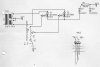
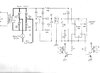
i've just picked apart my chlorinator and find the identical circuit. Mine has pacific-sel markings on the board; although the controller header is 2x5, not 6 pin (four pins are connected to 0v from the toroidal transformer) and the rectifier on the left of your drawing is a schottky SD241P like the other rectifiers.

If I understand the workings of this chlorinator correctly, the two power resistors are used for current monitoring across the electrolyser (via voltage measurements at pin 3 of the connector on your drawing).

I believe that the controller uses PWM (pin 4 on your drawing) to change the duty cycle on the mosfets, adjusting the voltage bit by bit to get an optimal current across the electrodes. Or rather an optimised V-I ratio as the lower the voltage the less overpotential being created.

this has two purposes I guess - if there is v low current then the device should shut off as there may be a build up of chlorine gas or a disconnect; if there is current but it is too low then the controller will keep hunting for an optimal voltage/current mix; and after a while go into a failure condition because there is insufficient salt, excessive scaling or degraded coating on the electrodes).

the current is then reversed periodically to descale the electrodes. the reversing happens by powering the relay coil attached to pin 5 of the header on your drawing.

I am not sure what pin 6 on the header is for; although measuring the voltage difference between pin 6 and pin 3 would give some useful information about the resistance between the electrodes which could be used, perhaps, for safety and measuring adequate salinity. and I also can't see the point in the multiple schottky rectifiers, mosfets and power resistors. redundancy i suppose - they are all carrying high power and so will generate heat. possibly the chosen components are only just in tolerance so sharing the load between them reduces service calls.


I doubt whether the design (at an industrial, low maintenance level) has changed much in terms of your search for a more modern version. but an idea at a hobbyist level might be to use a motor driver board that is high current and uses full n-mos h-bridges to avoid the heat costs in the p-mos chips. they are not expensive (£10 - https://www.robotshop.com/uk/cytron-13a-5-30v-single-dc-motor-controller.html). An advantage of these boards is that they also have PWM inputs to allow you to change 'speed' (voltage) and, of course, direction. so easily hooked up to an arduino, pi, esp32. you'd want a way to measure current. easy enough to do with an ACS712 (run one of the outputs from the motor board to the ACS712 and the from the ACS712 to the electrode.

For safety, you'd want to (have to) add a mechanical flow switch or a gas trap in the cell. again, a micro-controller is a good device for testing the state.

you can get ruthenium oxide coated titanium at sensible prices from ali-express. a decent chunk (suitable for a couple of 100m3 pools) seems to go for 250eur shipped. you'd need to pay import duty of course. then the components for the controller can probably be sourced for <£30. 3d print a mount for the electrodes and buy some PN16 fitments to house the electrode, some heavy duty wire for the cables to the electrode and it seems like you're done!

You do need a heavy duty transformer as well of course. but probably your existing system has one of those; as well as loads of heat sink material that you can reuse for other projects.

Just as a disclaimer - I have not tested the board I linked to, nor thought through every aspect of what might not work substituting an electrode for a motor; but it feels logical at first blush. Get proper advice before using!
 
Last edited:
I forgot to add that you will still need a rectifier if you want to power the whole solution from the main transformer.

But taking this a bit further, given the low price point here, you could also easily add a £15 orp probe and some simple electronics to condition the signal. and whilst you're at it, why not a ph probe and some controls for dosing bases and acids? a probe and a couple of peristaltic pumps would add only £30-£40. you'd then have a 'complete' wifi-connected pool management system for under £300 most likely.

is anyone interested in collaborating on a system design for this? schematics, board files, 3D print files etc. all to be open sourced.
 
The circuit diagram for a Chlorinator and the software to run it is attached.
 

Attachments

  • Chlorinator1.jpg
    Chlorinator1.jpg
    453.5 KB · Views: 661
  • Chlorinator1.txt
    615 bytes · Views: 353
  • ChlorinatorDescriptiont.txt
    1.8 KB · Views: 335
Bruwer

I will have a look more closely later but it seems you you powering the electrodes with AC. Typically at 50-60Hz.

I can't see how that works as it would not allow sufficient time for the cell to discharge before reversing. I've never seen a cell powered by AC before. I assume for this reason.
 
Hi,

I'm in to help building the opensource chlorinator. I can help in the part of control. I have knowledge with arduinos, ESP-12E, ESP32, ethernet modules, home assistant. I can help with the part of the electronics to control it, display, interface with MQTT via wifi or ethernet. Who can work with the power source module?
 
I'm interested in this project as well. Our salt system just got hit by lightning and I don't want to pay $1,500 to replace our Hayward system. I'm able to cobble things together from parts, can program a bit, and work with electronics. I would be happy to help out any way I can including building and testing a prototype.
 
Status
Not open for further replies.

Latest threads

New Articles From Microcontroller Tips

Back
Top