Continue to Site

Welcome to our site!

Electro Tech is an online community (with over 170,000 members) who enjoy talking about and building electronic circuits, projects and gadgets. To participate you need to register. Registration is free. Click here to register now.

  • Welcome to our site! Electro Tech is an online community (with over 170,000 members) who enjoy talking about and building electronic circuits, projects and gadgets. To participate you need to register. Registration is free. Click here to register now.

Cheap ebay RF modules made easy... (and fast!)

Status
Not open for further replies.
Hi,

I'm testing a transmitter-receiver circuit using the low-cost RF ones mentioned in this thread. I'm a little bit confused regarding how to configure the pins of the ATtiny 13 as input. Normally, when the pin is configured as input, without pull-up resistors enabled, it is tri-stated in High Impedance state.

So my question is: Do I have to connect a pull down resistor to the input pin of the microcontroller to make sure that it is at logic "0" when there's no data from the receiver ? From the circuits you've worked with, how do you connect the pins of the microcontroller which is to receive data from the receiver: pulled-up or pulled down with a resistor?

Thanks.
 
Most likely, the digital output from the module is push-pull, so you simply connect it to the MCU input with a straight wire with no resistors (may be a resistor in series for protection). But, of course, you should read the data sheet for the specific module to know for sure.
 
First of all, I apologize for my bad English. I will try to make small sentences.

Sensitivity or noise. What happens?

I bought some same kits from Ebay as shown on Mr RB's site.
I did not use it yet but I turned on the receiver. Frequently I receive some noise at the output.
I tried to understand what was going on, so I made a search on web and finally I found the circuit of the receiver.
Diagrama_kit_UHF_zpsynbwcx6x.jpg

I compared the amplifier and the comparator of the circuit with the receiver's kit. Pins 2 and 3 of U1:A (On R12)
Receptor_433MHz_Foto_1e1_zpskjokqaul.jpg

I analyzed the diagram and I measured what was going on the comparator’s input.

I found those signals showed bellow.
433XingLing_1_Ingles_zpsbyzcm7uj.jpg

Normally the instantaneous voltage of noise almost reaches the reference voltage. Occasionally it goes beyond the reference voltage and the output of comparator goes high.
I changed the value of R12 from 220k to 470k. See below.

433XingLing_3_Ingles_zpsxlcz5smc.jpg


Now the difference between the instantaneous voltage of noise and the reference voltage is bigger. I monitor the output of the receiver for 10 second and did not find any noise.

The value of R12 can be changed to 330k, if the earlier change was too much.

Thank you.

MOR_AL
 
You have reduced the sensitivity of the receiver to valid signals as much as you have reduced the propensity for no-signal noise.

To get the best performance on weak valid signals, the no-signal noise must be symmetric with respect to the ref voltage at pin 2. The fact of life with a super-regenerative receiver is that it puts out noise when it isn't receiving a signal, ergo, you must validate the output signal by using a preamble with a known pattern to validate what follows...

As a valid signal gets weaker, it will decode incorrectly, and begin to mimic the no-signal noise, so the messages must be short, and contain redundant information so the message can be recovered, or at least validated (ECC or Parity).
 
Yes!

I know that I reduced the sensitivity. But what would be the best signal to noise ratio of a data receiver?

Many years ago I projected a fiber optic receiver to receive weak data signals. As I had not experience, the gain of the receiver was big and noise signals became present.

In other words my receiver had much sensitivity but had much noise too. When I reduced de gain I could measure the error. During one month I sent and received (two transmitter-receiver modules) more than 5.e12 (2e6 * 60 * 60 * 24 * 30) pseudo random bits without one error.

I know that I reduced the sensitivity, but if you have sufficient signal you may reduce the gain.

I know that with super regenerative (SR) receivers is necessary to transmit a preamble right away before data to adjust the operation point of the RF transistor.

Below you can see the preamble changing the operation point of the RF transistor in a SR receiver that I projected.


Circuito_14_02_2011eee_zpsb4d5bab9.jpg


The 433MHz part of the receiver which catches the preamble.


Montagem_14_02_2011_zpszmr0xf1w.jpg


The diagram of the receiver until the point (V01) which I measure the preamble.(Ref. **broken link removed** )


Diagrama_esquemaacutetico_zpsmqoaws4j.jpg


In my application I want to receive one byte per hour (it is a water level system) or always its level changes one step.
I have to keep my uC as much as I can at sleep state until it receives data, not noise. With the presence of noise the uC awakes many times and it consumes a lot of electric energy.

PS. I will not continue with my receiver project. I will try to use the kit.

MOR_AL
 
Last edited:
hello is a pleasure to be part of the forum, I am new to electronics, I'm trying to understand the code of RomanBlack friend, this code can decode reception sender and image control ??

1445-MCO4339740995_052013-O.jpg


I do not much code, if this recepciona the input states TX (transmitter) where I see this recepcionando data ?? or that port pic I can see the codes obtained ?? Im really confused, try to redirect the code obtained an LCD does not work me, if someone help me, thanks


Code:
(PIC 18F2550 ---- Xtal 8Mhz)

sbit LCD_RS at RA5_bit;
sbit LCD_EN at RA4_bit;
sbit LCD_D4 at RA0_bit;
sbit LCD_D5 at RA1_bit;
sbit LCD_D6 at RA2_bit;
sbit LCD_D7 at RA3_bit;

sbit LCD_RS_Direction at TRISA5_bit;
sbit LCD_EN_Direction at TRISA4_bit;
sbit LCD_D4_Direction at TRISA0_bit;
sbit LCD_D5_Direction at TRISA1_bit;
sbit LCD_D6_Direction at TRISA2_bit;
sbit LCD_D7_Direction at TRISA3_bit;

char texto2[10], texto1[]="Data Receiver";

unsigned char rxdat[10]; // (global var) holds received RF bytes

//=============================================================================
// RECEIVE_RF_PACKET
//=============================================================================
void main(void)
{
//-------------------------------------------------------
// This function receives an RF packet of bytes in my pulse period
// encoded format. The packet must have 10 valid contiguous bytes
// or the function will not exit. There is no timeout feature, but could be added.
// global variable; unsigned char rxdat[10] holds the 10 byte result.
// Note! TMR0 is running at 500kHz, so 200uS = 100 TMR0 ticks
//-------------------------------------------------------
unsigned char rrp_data;
unsigned char rrp_period;
unsigned char rrp_bits;
unsigned char rrp_bytes;

TRISC.RC6 = 0; // TX pin, works fine with/without setting this I/O in proteus
TRISC.RC7 = 1; // RX pin, works fine with/without setting this I/O in proteus
CMCON = 0x07;
ADCON1 = 0x0F;
Lcd_Init(); //Inicializa el LCD.
Lcd_Cmd(_LCD_CLEAR); //Borra el display.
Lcd_Cmd(_LCD_CURSOR_OFF); //Apaga el cursor.
Lcd_Out(1,6,texto1); //Escribe el texto1.

rrp_bytes = 0;
while(rrp_bytes < 10) // loop until it has received 10 contiguous RF bytes
{
//-----------------------------------------
// wait for a start pulse >200uS
while(1)
{
while(!PORTC.F7) continue; // wait for input / edge
while(PORTC.F7) continue; // wait for input \ edge
rrp_period = TMR0L; // grab the pulse period!
TMR0L = 0; // and ready to record next period
if(rrp_period < 100) rrp_bytes = 0; // clear bytecount if still receiving noise
else break; // exit if pulse was >200uS
}

//-----------------------------------------
// now we had a start pulse, record 8 bits
rrp_bits = 8;
while(rrp_bits)
{
while(!PORTC.F7) continue; // wait for input / edge
while(PORTC.F7) continue; // wait for input \ edge
rrp_period = TMR0L; // grab the pulse period!
TMR0L = 0; // and ready to record next period

if(rrp_period >= 100) break; // if >=200uS, is unexpected start pulse!

if(rrp_period < 61) rrp_data.F0 = 0; // 61 = 122uS
else rrp_data.F0 = 1;
rrp_data = (rrp_data << 1); // save the good bit into rrp_data
rrp_bits--; // and record 1 more good bit done
}

//-----------------------------------------
// gets to here after 8 good bits OR after an error (unexpected start pulse)
if(rrp_bits) // if error
{
rrp_bytes = 0; // reset bytes, must run from start of a new packet again!
}
else // else 8 good bits were received
{
rxdat[rrp_bytes] = rrp_data; // so save the received byte into array
rrp_bytes++;
// record another good byte was saved


bytetohex(rrp_data,texto2);
lcd_out(2,1,texto2);
delay_ms(50);

}
}
}
//-----------------------------------------------------------------------------


or I can redirect data to hyperterminal?
 
Last edited by a moderator:
I just saw this thread and have a comment. On the project page, about 1/4 down from the top, are scope shots of the receiver output for three different modulating frequencies. The conclusion is that there is a receiver problem causing duty cycle distortion at higher data rates. I respectfully submit an alternate interpretation of the data.

At 1.00 kHz, the output duty cycle is 47%, a 3% distortion. But that also is a 30 us distortion. At 10 kHz it looks like the duty cycle is about 25%. But, if you measure the positive pulse width, add in the 30 us distortion from the slower waveform, multiply by 2, and invert, you get 9.1 kHz. This suggests to me that the duty cycle distortion is caused mostly by the startup time delay of the transmitter, which is completely off during zero states, and is a constant that is relatively independent of the modulating frequency. I suspect that there is a similar constant time delay distortion caused by the receiver at the end of a received pulse.

In no way do I think that this is the whole answer, both because RF never is simple and because cheap parts are, well, cheap. But I wonder what the modulated RF envelopes look like superimposed over those three input data waveforms with the scope triggered on the data, and superimposed over the output waveforms with the scope triggered on the RF. They might show the two processing delays I'm theorizing, and suggest a pre-distortion that can be calculated automatically for any input data rate to improve system reliability.

ak
 
Last edited:
What every day life purpose is the transmitter & receiver good for? What is 433 MHz and 315 MHz used for in every day life? What distance will it transmit?
 
What every day life purpose is the transmitter & receiver good for?
key fobs, garage doors, gates, remote doorbells, remote temperature/weather stations, remote telemetry, dog training, etc

What is 433 MHz and 315 MHz used for in every day life?
They are license-free (ISM) bands for just this purpose. Only infrequent, very low power, short duration transmissions allowed, no voice, no continuous broadcasts.

What distance will it transmit?
With good antennas, a few hundred feet. With crummy or no antennas, a few feet.
 
I thought those were the CB radio bands?
 
Good day Mr RB,

I have a small doubt detecting your Very First start pulse on receiving packet data.
By detecting Hi to low (Falling edge) you start TMR0 & it will start counting the pulse period until another falling edge is detected.

On the very first receiving start pulse, there is no falling edge to start the timer (Reset TMR0). The very first falling edge will appear after the High period of 80uS of the start pulse. At that time the TMR0 value is invalid because not RESET after a previous falling edge (There is no any previous falling edge on very first). Because these modules in idle state it stays in logic low.

The attached code is waiting for a valid start pulse, but it will never achieve. You got it what I mean...!! I think you need a preamble byte (Like 12mS High pulse to settle gain & reset TMR0) to be send first prior to send the data packet with start bytes.

Code:
{
   //-----------------------------------------
   // wait for a start pulse >200uS
   while(1)
   {
     while(!PORTC.F7) continue;    // wait for input / edge
     while(PORTC.F7) continue;     // wait for input \ edge
     rrp_period = TMR0L;           // grab the pulse period!
     TMR0L = 0;                    // and ready to record next period
     if(rrp_period < 100) rrp_bytes = 0;   // clear bytecount if still receiving noise
     else break;                   // exit if pulse was >200uS
   }
 
Last edited:
Thanks for educating me. The priceless attitude of who takes time and dedication to teach us.

Am after modifying these 315MHz receiver units to work OOK at half or less the receiver frequency. Do you see reasons that by tweaking the tuning components will not be enough to make them work around 140MHz even at somewhat reduced performance ?
There is a few types and in superheterodyne and regenerative modes. If some have schematic showing more hack friendly, well, that one.
Any guidance or link to someone doing that will be appreciated.

Obviously it would be illegal to that, you're only allowed to use specific licence free bands, which vary depending on your country.

And wiping out the 2M amateur band is going to swiftly find you in hot water with the authorities, as amateurs have the skill and technology to easily track you down.
 
¿? What is 'wiping out' the 2m band by modifying a receiver, and what is obviously illegal there, even if would not have my two amateur radio licenses ?
 
¿? What is 'wiping out' the 2m band by modifying a receiver, and what is obviously illegal there, even if would not have my two amateur radio licenses ?

Super regenerative receivers emit masses of interference, the more expensive superhet ones 'should' be somewhat better.

However, your ham licence (and mine) almost certainly doesn't cover the use of such crude and nasty devices, as you should be aware if you've gained an amateur licence.

Anyway,if you're not modifying the transmitters as well, what are you hoping to use the receivers for?.
 
The "masses of interference" emitted by those receivers are then "covered the use of such crude and nasty devices" available to the general public with no licenses as am aware of that buy these units to play with, but not for our amateur radio activity ?
Am not modifying any transmitters, do not care about them, and the operation is for OOK presence detection, and still see nothing illegal.
 
The "masses of interference" emitted by those receivers are then "covered the use of such crude and nasty devices" available to the general public with no licenses as am aware of that buy these units to play with, but not for our amateur radio activity ?

The licence free band isn't full of radio hams (like yourself) trying to receive weak signals from great distances.

Am not modifying any transmitters, do not care about them, and the operation is for OOK presence detection, and still see nothing illegal.

As long as you use superhet receivers there should be no issue? - and if you can find (or draw out) the schematic, then it should be obvious what you need to alter (front end tuning, and local oscillator).
 
If you are detecting signals within one of the Amateur bands, then something must be transmitting them?
That transmitter must comply with the national licencing rules - power, frequency, spurious emission and identification in every transmission:


As Nigel says, any superregenerative receiver can be very dodgy item - they can be used and sold commercially, but each specific type needs FCC or equivalent certification before it can be sold, to ensure it does not cause harmful interference.


Equipment you build yourself for use in the Amateur bands is exempt from the certification rules, but it's also a part of the Amateur licence conditions that you test any device you build to ensure there are no spurious emissions at unreasonable levels.
Superregen types are quite common in simple DIY Amateur band receivers, but need extremely careful setting up to avoid problems.


Re. modifying commercial devices, the ones we have used in products have been FM types and all have SAW filters to define the operating frequency so they could not be modified. They are also vastly more complex than any cheap ebay modules.
The ones we have used are similar to such as this http://www.radiometrix.com/wrx2-0


I know there are a lot of cheaper & lower quality ones about, but I do not know offhand just how practical they are to mod for a drastically different frequency.

>google<

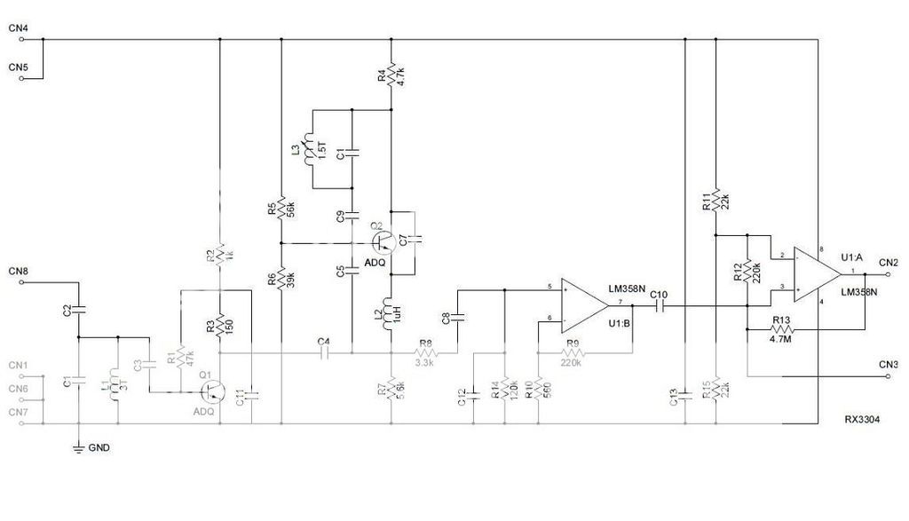
It looks like there are two very common types of cheap AM / OOK 315 & 433 MHz receiver modules on ebay.

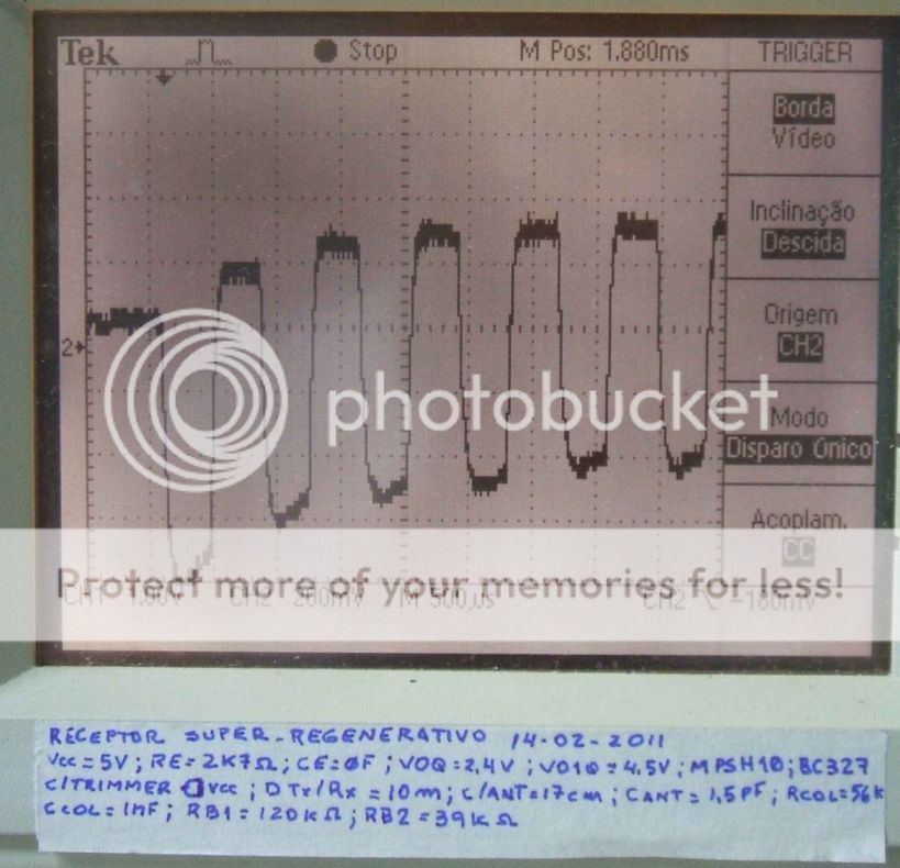
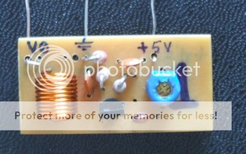
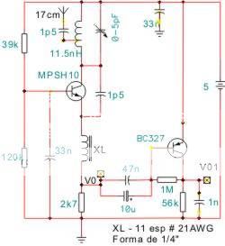
The simpler ones are superregenerative, and the circuit for those is freely available.
The transmitters are SAW based but the receivers just use a couple of tuned circuits.
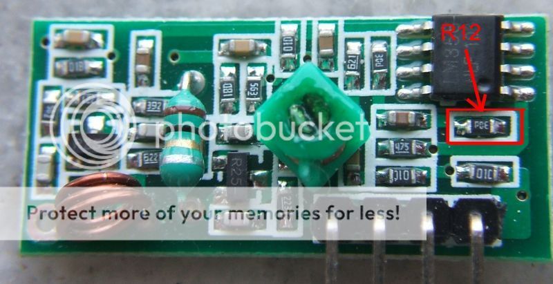
Pictures and schematics in this listing: http://forum.hobbycomponents.com/viewtopic.php?t=1324

Modifying those receivers for 2m should be a doddle, but I'd not use them after modding until I'd very thorough checking for spurious output - and there is no way of knowing if they are even legal in the first place.
In fact that seems very unlikely - looking up their type number "MX-05V" brings up masses of similar items, but nothing like them if searched for in conjunction with FCC ID or Type approval (The UK certification).

Personally I'd put it in a die cast box with an antenna connector screwed through the wall & filtered signal connections, no matter what other testing I did!


The other common ones are superheterodyne modules and slightly more sophisticated - but the receiver IC they all seem to use is designed for the 300 - 440MHz range, so they cannot be re-tuned to 2m.
eg. These
**broken link removed**

Which use this device:


If you want a decent, simple, 2M AM receiver, look at something like this - two ICs and a few components:

Or, a simple tuned front end and mixer that shifts the 2M signal to either 315 or 433 so one of the cheap superhet modules can be used as first IF and demodulator???

[Also with two Amateur licences - G8TBF & G0WTK].
 
Status
Not open for further replies.

Latest threads

New Articles From Microcontroller Tips

Back
Top