Continue to Site

Welcome to our site!

Electro Tech is an online community (with over 170,000 members) who enjoy talking about and building electronic circuits, projects and gadgets. To participate you need to register. Registration is free. Click here to register now.

  • Welcome to our site! Electro Tech is an online community (with over 170,000 members) who enjoy talking about and building electronic circuits, projects and gadgets. To participate you need to register. Registration is free. Click here to register now.

change rotation speed | standard clock part

Status
Not open for further replies.

oem_odm

New Member
hi all

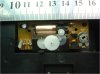
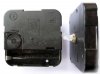
is there an easy way to speed up a standard clock module part (please see attached JPG picture).

- would like it to turn 3 times faster.
- can add any extra external circuit
- can increase the voltage i.e. 2 x AA instead of one

i know v. little about electronics.

Also important to know how this will affect the power consumption....

thanks
 

Attachments

  • CLOCK_MODULE.jpg
    CLOCK_MODULE.jpg
    84.1 KB · Views: 187
You could remove the 32Khz crystal and drive the IC with an external oscillator at 3X the frequency. You could also sub an LC circuit or higher frequency crystal for the original. Changing the battery voltage will not speed it up 3x. Is this a prop for a time bender movie?
 
You can drive the clock mechanism solenoid directly from a 555 timer pin3 output, use a series cap so it makes AC through the solenoid and a series resistor to cut the current right down as they only need a couple mA.

Put an adjuster pot on the 555 and you have a clock at any speed you like... :)
 
What's up doc? This may give you an idea about what's inside. Ideally you could replace the crystal with a 3x32KHz oscillator, or disconnect and drive the coil with a 2-phase circuit that would replicate the pulse pattern shown...but I've never been able to get one apart and back together with the gear-train intact. :( Maybe someone else has, and can describe how they did it. :)

Ken
 
Last edited:
new picture for the problem

hello everyone..thanks for your feedback. i;ve attached a better picture showing what i'd like to achieve (but dont understand much... )

What you see is the back end (opened) of a clock meachanism, mounted to a pcb (its power pins connect with pcb power slots) - so it turns and turns.

What could be changed on the PCB to increase the speed of rotation..rough 3 times faster? I would love a simple drawing with arrows on the picture i've provided.....any help would be realy appreciated...

thanks again
 

Attachments

  • clock_module_2.jpg
    clock_module_2.jpg
    409.7 KB · Views: 193
Hello Mr Rb, thankyou for your ideas - i dont understand much as im not that well informed with electronics. would you mind checking my last reply which shows the back end open of the module + a rough PCB...would you mind drawing on it what could be changed...maybe roughly draw a line where/how you would connect things differently...it would be really appreciated - thank you :)
 
Any idea what the little variable resistor (the thing with the screwdriver slot, below "VDD") is for? The circuit looks like it may be a crystal-controlled transistor multivibrator. Is it old? All the ones I've seen have an integrated circuit covered with a blob of black epoxy..with only a crystal and a capacitor for external components.

Ken
 
Last edited:
hello ken

thankyou for your response.

i don;t know what it is..really and its a cheap system i think. What do you think is the best way to change the speed..in your best educated guess?.....maybe some little drawing to help guide me... thanks again ken
 
The trimpot is pretty common it gives a small variation to the osc speed, it lets them use really cheap nasty xtals and adjust the clock via trimpot. Lots of those cheap clocks have the trimpot brought out to a little dial on the back for tweaking the clock speed.

A large change in the speed will require a new xtal, maybe new cap values too.

Or just make a 555 oscillator like I said before. :)
 
hello Mr RB, would you mind making a quick photoshop/paint drawing to explain your 555 oscillator idea..please? no rush..just would like to understand your idea 100%
 
You get any 555 oscillator schematic (there's tons on this forum) then connect the output pin through a resistor (maybe 1k), then through a cap (maybe 1 uF) then to the clock coil. The other side of the clock coil is ground, ie the 555 ground.

All it does is make small ac pulses through the coil when the 555 output pin changes state.
 
You could achieve three times the speed through gearing, might be an option for you.

Personally I would try this solution; saves having to fiddle about with making extra circuits and finding a space for them in the casing. The electronics would be the same, but the mechanics would be altered to triple the speed. Assuming that it would still have enough torque after the step-up, but it doesn't exactly take much force to turn a clock.

Only problem may be the requirement for suitable replacement gears, which may well be difficult to find.
 
hi giftiger_wunsch - i prefer the electronics solution becuase bolting on an extra pcb is alright..so still fiddling about with that

i see your point about gearing, it might make sense...the toruble is finding the right gears and sizes so they mesh up perfectly using the exisiting gear shafts..

thanks for your input :)
 
finding the right gears and sizes

Indeed, that is the main drawback to the mechanical approach. If you prefer the electronic approach, Mr RB's suggestion is a good one. A 555 oscillator circuit is simple and effective.

Good luck.
 
Status
Not open for further replies.

Latest threads

New Articles From Microcontroller Tips

Back
Top