Continue to Site

Welcome to our site!

Electro Tech is an online community (with over 170,000 members) who enjoy talking about and building electronic circuits, projects and gadgets. To participate you need to register. Registration is free. Click here to register now.

  • Welcome to our site! Electro Tech is an online community (with over 170,000 members) who enjoy talking about and building electronic circuits, projects and gadgets. To participate you need to register. Registration is free. Click here to register now.

CDI Ingnition System - Please Help Me Build One

Status
Not open for further replies.
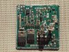
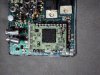
Just curious Is the internals of the module acessable? What is the fault with the unit? not working at all or only 2 cylinders firing? It may just be possible to repair the module. I would suspect the most likely components to fail are the SCRs which fire the coil, or the HV inverter. A good clear photo of both sides of the module board would be a help.
 
Last edited:
The module was encase in rubber compound so i had to use acetone and leave it over night. It did desolve the rubber but it also desolve some of the components i kinda over did it. I was trying to recreate the circuit and build my own, but some components had no info on them because their too small. Also my solder iron was way too big. I decided to try another route and build from scratch. I cut the top level off the circuit board to get a look below, i think i screw that board up...lol
 

Attachments

  • DSC07935-1.jpg
    DSC07935-1.jpg
    147.4 KB · Views: 790
  • DSC07939-1.jpg
    DSC07939-1.jpg
    117.3 KB · Views: 789
I don't think this is a CDI ign at all, more like a transistor switching Ign system. The timing would be adjusted with that processor. My approach to exposing components is carfully diging not dissolve the poting compound. Ive had to work on a mates Kawasaki KZ1000 with a faulty Main & Pump relay module as they were no longer available. .
 
This is the circuit of a KZ 1000 1982 EFI model & the IGN system looks similar. The ign module has a 10 pin connector.
 

Attachments

  • Kawasaki KZ1000 1982 EFI.bmp
    816.6 KB · Views: 1,412
I didn't get a chance to post the schematic but will later today. I think the unit is described as a IC Igniter component. I checked the 10-pin connection for internal resistance check against the manual and found pins 1-3 not within spec, but not sure if that’s my meter not reading right or the IC Igniter is somewhat bad.
 
Will have to spend more time troubleshooting the rest of the ignition system, like the pick-up coils resistances, plug coils on the primary and secondary, any lose ground wires, shorting wire, etc.
 
I noticed 2 transistors on the board D1071 these are NPN darlington transistors 450V @ 6Amp switching. These are most likely the Ign coil switching, check these are ok. Also these bikes if dropped on there right side can damage the bottom pickup coil & cause intermittent spark problems.
 
Last edited:
I previously did check the pickup coils and test within spec against the owner’s manual. Yes they are D1071 transistors; I’m not able to test them while installed so getting them out is very difficult because there surface mount type. These transistors don’t have a cross-reference that matches but some are close. Right now I’m working through my coils, spark plugs, and wiring to see if any of those may also have problems. This bike road straight for 2 years every workday rain or shine, 2-hour round trip from work. I’m not sure if it’s a quensident but it started just when it was getting hot here in AZ.
 
2SD1071 transistors are available on ebay quite cheaply. Have seen quite a few pickup coils test fine with a multimeter, & still not work. Since there is 2 coils did the bike start running on only 2 cylinders or not run atall?
 
originally the bike started to run a bit rough so i decided to do the plugs, wire and card cleanout. after that it wouldn't start. I started toubleshooting and lead me to the IC Igniter. I put-out one from my other bike, smaller and different part number on the IC Igniter. It fire right up but would run rough after 4 to 5k rmp. I knew then it was most likely the IC Igniter.
 
Not sure if you have solved this or not but I run a 83 kz750 gpz which uses similar setups as its little brother the 550gpz. Anywho here is a setup I found for the same issue. I happen to see your post as I skimmed through some electronics forums for automotive applications. So I signed up. :) Hope this helps you as it did got me. Oh and upon further reading there are several other bikes info added like the zr1.

Authors list of useful mods and information: **broken link removed**
Working Module diagram: **broken link removed**
Bench testing results:**broken link removed**
**broken link removed**
 
Last edited by a moderator:
Status
Not open for further replies.

Latest threads

New Articles From Microcontroller Tips

Back
Top