Continue to Site

Welcome to our site!

Electro Tech is an online community (with over 170,000 members) who enjoy talking about and building electronic circuits, projects and gadgets. To participate you need to register. Registration is free. Click here to register now.

  • Welcome to our site! Electro Tech is an online community (with over 170,000 members) who enjoy talking about and building electronic circuits, projects and gadgets. To participate you need to register. Registration is free. Click here to register now.

CD4553-14511-3 digit seg

Status
Not open for further replies.
upload_2016-3-8_23-16-54.png

upload_2016-3-8_23-18-18.png
upload_2016-3-8_23-19-12.png

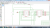
The blue lines are meant to represent a push to make switch for reset and clock.

Note: please do tell me if it is not clear and messy to redo. Function of circuit to count coins
Incase the picture were not clear enough I added more specific parts.
I got the bases of this circuit from: https://www.kitsrus.com/pdf/k1.pdf (has clearer schemaitic)
There a couple of issues with this circuit that I would like to discuss:

1) What is the carry and what do I place there?
2) What is the latch is it a flip-flop? what doIplace there aswell:
3)DS3 in the link is not used why?
4) The way i used the diode compared to the picture; is that appropriate?
5) Transistors, what pin would they connect to to 7 seg as both pins are either CC or DP and its not the DP, its common cathode but their both CC?
6) Simply, would this work in practice? (excluding debouncing as that I have a circuit for)


Thank you very much for helping and reading this!
 

Attachments

  • upload_2016-3-8_23-17-16.png
    upload_2016-3-8_23-17-16.png
    94.3 KB · Views: 309
The pdf file you linked to has the schematics blanked out.

The Carry (also called overflow on some datasheets) is used for cascading more counters. For example if you wanted a six digit counter, you would use two counter chips, and you would feed the carry out from the first counter to the clock input of the second one. In your case, just leave it unconnected.

The Latch input is used to freeze the displayed count. In your case, it should be connected to ground.

I don't know why DS3 would not be used. It appears to be an error in the schematic. DS1, D32 and DS3 should be connected to the base resistors on the three transistors.

I can't comment on your use of the diode, because I can't see the original schematic. It may be there to protect the circuit from having the power supply polarity accidentally reversed.

The transistor collectors should go to the cc (common cathode) connection on the displays. I don't understand the confusion here.

Your schematic is too fuzzy to trace out in detail, but it should work assuming you have everything hooked up correctly.
 
Yes, the diode is for reverse polarity protection, something very useful for the vendor of a general purpose kit but not necessary for your circuit to operate - as long as you wire up the power correctly.

Note that the 4553 digit select outputs are active-low, and that the three digit driver transistors are configured as emitter followers, not saturated switches. For this reason, the three base resistors can be eliminated, or at least reduced to 1K or less, to reduce the display brightness changing as a function of how many segments are on.

ak
 
The pdf file you linked to has the schematics blanked out.


The transistor collectors should go to the cc (common cathode) connection on the displays. I don't understand the confusion here.

.

What I meant was that there are two CC pins so do I connect them both from each segment to their transistor or only one?
 
Yes, the diode is for reverse polarity protection, something very useful for the vendor of a general purpose kit but not necessary for your circuit to operate - as long as you wire up the power correctly.

Note that the 4553 digit select outputs are active-low, and that the three digit driver transistors are configured as emitter followers, not saturated switches. For this reason, the three base resistors can be eliminated, or at least reduced to 1K or less, to reduce the display brightness changing as a function of how many segments are on.

ak

Would just like to confirm; Does the DP Pin on the 7 seg go to ground?
 
You can leave the DP (decimal point) pin unconnected unless you want to have one of the the decimal points lit, in which case it would be connected to +5 volts.
 
You can leave the DP (decimal point) pin unconnected unless you want to have one of the the decimal points lit, in which case it would be connected to +5 volts.
Through a current-limiting resistor.

Yes, the two Common pins are connected together.

ak
 
Last edited:
Status
Not open for further replies.

Latest threads

Back
Top