Hi, all!
New to the firum and happy to have found it!
I am a hobby machinist and I am starting to add ALuminum Annodizing to my home hobby shop. The method I will be using requires a controlled current power supply for best results, but they are fairly expensive. ($3-400)
My requirements (ideally) are a 0-15V, 0-3A CC unit. Most units like this also seem to have Variable/controlled Voltage, but that is not a necesity for this dedicated power supply. I need to maintain a controled current density and let the power supply vary the voltage as the annodic material varies its resistance [as coating is deposited].
Whe the resitance peaks and the voltage starts downward....voila! She is done! For this part, a meter would be nice. I guess an built-in curent meter would be nice, too. ALthough both could be digital to keep costs down.
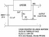
I can construct almost anything so if anyone has a schematic for such a power supply I woud greatly appreciate a look at it.
New to the firum and happy to have found it!
I am a hobby machinist and I am starting to add ALuminum Annodizing to my home hobby shop. The method I will be using requires a controlled current power supply for best results, but they are fairly expensive. ($3-400)
My requirements (ideally) are a 0-15V, 0-3A CC unit. Most units like this also seem to have Variable/controlled Voltage, but that is not a necesity for this dedicated power supply. I need to maintain a controled current density and let the power supply vary the voltage as the annodic material varies its resistance [as coating is deposited].
Whe the resitance peaks and the voltage starts downward....voila! She is done! For this part, a meter would be nice. I guess an built-in curent meter would be nice, too. ALthough both could be digital to keep costs down.
I can construct almost anything so if anyone has a schematic for such a power supply I woud greatly appreciate a look at it.