Continue to Site

Welcome to our site!

Electro Tech is an online community (with over 170,000 members) who enjoy talking about and building electronic circuits, projects and gadgets. To participate you need to register. Registration is free. Click here to register now.

  • Welcome to our site! Electro Tech is an online community (with over 170,000 members) who enjoy talking about and building electronic circuits, projects and gadgets. To participate you need to register. Registration is free. Click here to register now.

Car Alarm modification

Status
Not open for further replies.

rups22

New Member
Hi all

I have installed a fairly cheap chinese branded alarm system in my van.
The side door triggers activate when they detect the voltage goes from 12v to 0v
The door triggers are very sensitive to any fluctuation in voltage and are giving false alarms.
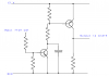
I am hoping to use analog circuitry to, for example only trigger the alarm when the 12v goes to 0v for more than 2 seconds.

Can this be done or do I need to go down the microcontroller route?

Thanks in advance

Side Door Trigger.png
 
The alarm is expecting that the wire connected to the interior light is held a 12 V when the doors are closed. The circuit they show has an incandescent bulb holding the wire at 12 V.

If:-
1) Your car has LED interior lights, or
2) the door switches only go to a control box, or
3) the power to the interior light is removed after some time
then the alarm may false trigger.

I suggest that you try a resistor, 1k Ohm would be fine, between the battery feed and the door trigger. The resistor will keep the voltage up near 12 V and there should not be any more false alarms.

That alarm is designed to fit cars that have got all the door switches wired together, and directly connected to the interior light. I don't think I've owned a car like that in the last 20 years, maybe 30, as all modern cars have LED interior lights, fading on and off of the lights, a delay after closing the door before the lights go out, a timer to shut off the interior lights if a door is left open or any combination of those. The electronics in modern cars do all sorts of things with the interior light that would stop that alarm working in the intended way.

Yes you are quite right my car is a 1999 Mercedes with no alarm or central locking hence this project :p
Yes, the input to the alarm unit is spliced using the interior dome light circuit (No LEDs!)

In the schematic, you should see the door fascia switch. This is a Push to Break switch.
I've used a multimeter and I was wrong about 12v, it's actually around 3v.

When all car doors are closed, the voltage input to the alarm unit is around 3v, but opening the door breaks the circuit and gives around 0v

I've tried the resistor but no luck. I believe the voltage is dropping to 0v for a millisecond before recovering which causes the false alarm.

Finding a problem in the original Mercedes wiring harness is not really an option so I'm looking to overcome this issue using other options

(Ignore negative voltage in photos, my multimeter cables were reversed)
 

Attachments

  • IMG_0947 2.jpeg
    IMG_0947 2.jpeg
    1.3 MB · Views: 192
  • IMG_0948 2.jpeg
    IMG_0948 2.jpeg
    1.3 MB · Views: 189
As the voltage is only changing from 0 - 3 V, and the alarm is looking for 0 - 12 V, it is not likely to work properly.

I suggest a circuit like this. The capacitor will slow it down as well, so if there are short glitches, they will not be noticed by the alarm.
 

Attachments

  • alarm.png
    alarm.png
    18.6 KB · Views: 204
Status
Not open for further replies.

Latest threads

Back
Top