Continue to Site

Welcome to our site!

Electro Tech is an online community (with over 170,000 members) who enjoy talking about and building electronic circuits, projects and gadgets. To participate you need to register. Registration is free. Click here to register now.

  • Welcome to our site! Electro Tech is an online community (with over 170,000 members) who enjoy talking about and building electronic circuits, projects and gadgets. To participate you need to register. Registration is free. Click here to register now.

Capacitors and PowerDissipation

Status
Not open for further replies.

vne147

Member
Hey everyone. This is probably a pretty basic question for some but I'm not sure of the answer. Basically, I'd like to know how to determine a capacitor's power dissipation capability. I did a quick Google search but didn't find any clear answers. One site said that ESR was a measure of power dissipation capabiltiy and another said that ripple current was.

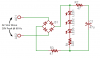
I'm thinking about using this 25V 47µF cap in an LED circuit. I simulated the circuit and the cap's power dissipation is going to vary. The graph of power dissipation essentially looks like a full wave rectified sine wave at 60 Hz and according to simulator, the cap will have a peak power dissipation of 360 mW. How do I know which caps would be suitable? Thanks in advance for the assistance.
 
I'm pretty sure I can say that a capacitor doesn't dissipate any effect. It only store energy, which it later on is supposed to deliver to some other resitive component.

However A capacitor vould have a volt x ampere for a given sinus formed AC with a given frequenzy. But this is not dissipated effect.
 
I felt capacitors was hot when they at work, I guess this is the energy dissipation.

In practice, the equivalent resistance is the main reason for energy loss caused by capacitance, dielectric loss is usually ignored.
General capacity tester can measure it, the LCR bridge can also measure it.
 
For electrolytics it is ripple current. Your spec. is not to well marked, but the ripple current is the number on the right of the case size. In your case 79 ma.
 
vne147,

Hey everyone. This is probably a pretty basic question for some but I'm not sure of the answer. Basically, I'd like to know how to determine a capacitor's power dissipation capability.

You do not determine what the capacitor's maximum power dissipation is, the manufacturer does. Perhaps you should read the link below. It give an example calculation of a capacitor dissipation in a circuit.

Ratch

**broken link removed**
 
There is leakage and AC ESR for a cap. It depends on dielectric used. For ceramic caps the ESR is generally worse the higher the dielectric K of ceramic mix used. Higher K material is used for higher value caps. Higher K usually has lower breakdown voltage for a given thickness dielectric. Low ESR ceramic caps are porcelain. Mylar and polyethylene dielectrics have low ESR.

Electrolytics caps have a sponge cellular structure which has a higher ESR. Electrolytics don't like a lot of ripple voltage which translates to a lot of ripple current through the cap, which translates to heating. The more the heating, the more the internal pressure, the faster the electrolytic paste dries out, and shorter the cap lifetime.
 
For electrolytics it is ripple current. Your spec. is not to well marked, but the ripple current is the number on the right of the case size. In your case 79 ma.

ronv,

I see the number that you're referring to and you're right, it's poorly marked. I wondered what those numbers were. I'm using the 25V cap so I think the ripple current would be 83 not 79. That aside, what do I do with that value? How does that tell me if the cap would be OK or not?

vne147,


You do not determine what the capacitor's maximum power dissipation is, the manufacturer does. Perhaps you should read the link below. It give an example calculation of a capacitor dissipation in a circuit.

Ratch

**broken link removed**

Ratch,

I didn't mean to suggest that I'd be determining the maximum power dissipation capabilty of the cap. What I meant to say was how can I tell if a specific cap's power dissipation capabilty is greater than what it will experience in the circuit. I read the link you provided and while it was informative, unless I missed something, it didn't really answer my question. It was an explaination about how to determine how much power a cap will dissipate for a given set of conditions but not how much power that cap can dissipate. I'm sure I can just build the circuit and see if the cap gets hot or not but I'm sure there is a better way to go about component selection than that.


I posted a schematic of the circuit the cap will go in. Can anyone say if the cap I linked to in my original post is suitable? If not, can someone suggest an alternate one? Thanks everyone for the input.

under-cabinet-lighting-png.46100
 

Attachments

  • Under Cabinet Lighting.png
    Under Cabinet Lighting.png
    13.3 KB · Views: 447
In your original post you said you had run a simulation. Instead of using the simulation to determine the "power dissipation" in the cap, determine the RMS value of the ripple current in the cap and see if it's below 83 mA.
 
In your original post you said you had run a simulation. Instead of using the simulation to determine the "power dissipation" in the cap, determine the RMS value of the ripple current in the cap and see if it's below 83 mA.

Ahhhhh, that makes sense now. So as long as the current the cap recieves while charging or provides while discharging is below the ripple current, I'm OK. Is that right? The simulation showed a maximum current of ~ 30 mA while charging and ~ 13 mA while discharging. So I take it the cap I linked to in my original post is good. Thanks!
 
Hi vne,
Your schematice says 18 volts peak, but I bet it means 18 volts peak to peak or the voltage will be too high for your cap.
But in either case the ripple current is ok.
 
Ahhhhh, that makes sense now. So as long as the current the cap recieves while charging or provides while discharging is below the ripple current, I'm OK. Is that right? The simulation showed a maximum current of ~ 30 mA while charging and ~ 13 mA while discharging. So I take it the cap I linked to in my original post is good. Thanks!

You need to use the RMS value of the current through the cap; given your max values, the RMS value will undoubtedly be less than 81 mA. It would be a good idea to check the ripple current through the actual cap. Measure the voltage across R2 with an RMS reading voltmeter, and use ohm's law to calculate the current.
 
You need to find the capacitor manufacturers rating (confirm on your own if you wish). Also, caps have a thermal derating.
 
Hi vne,
Your schematice says 18 volts peak, but I bet it means 18 volts peak to peak or the voltage will be too high for your cap.
But in either case the ripple current is ok.

Ronv,

It's not 18V peak to peak, it's 36V peak to peak. However, the voltage the cap sees will be rectified. After the voltage drop across the diodes in the bridge rectifier and 47Ω resistor, the max voltage the cap would ever see shouldn't exceed 12V - 13V. Is that not correct?

You need to use the RMS value of the current through the cap; given your max values, the RMS value will undoubtedly be less than 81 mA. It would be a good idea to check the ripple current through the actual cap. Measure the voltage across R2 with an RMS reading voltmeter, and use ohm's law to calculate the current.

I didn't bother calculating the RMS value when I saw the peak was well below the ripple current. Like you said, it's impossible for an RMS value to be greater than the peak value. But I'll make sure to measure the current on the physical circuit once built. Thanks!

You need to find the capacitor manufacturers rating (confirm on your own if you wish). Also, caps have a thermal derating.

Which rating? The max power dissipation? Do I have to write the manufacturer because most if not all of the data sheets I've looked at didn't have that in them.
 
With capacitors it's all about the temperature rise. The manufacturer will be able to provide the needed info... if they can't, you probably don't want to be using "them".
 
Status
Not open for further replies.

New Articles From Microcontroller Tips

Back
Top