Continue to Site

Welcome to our site!

Electro Tech is an online community (with over 170,000 members) who enjoy talking about and building electronic circuits, projects and gadgets. To participate you need to register. Registration is free. Click here to register now.

  • Welcome to our site! Electro Tech is an online community (with over 170,000 members) who enjoy talking about and building electronic circuits, projects and gadgets. To participate you need to register. Registration is free. Click here to register now.

Capacitor Repair on a Jeep

Status
Not open for further replies.

John55657

New Member
Hi all,

Sorry if this is the wrong section, but I have a very limited experience, but my ECU received loads of water last year, and my Jeep is having intermittent issues. I narrowed it down to the capacitors in the ECU wreaking havoc on the car. (Making the relays go nuts etc.. )

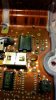
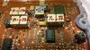
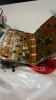
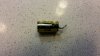
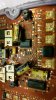
My question is.. I was able to take the three capacitors out, but I pulled too much on one, and I lifted a part of the board. (Please see attached)

Any help on knowing if there is a way to test if I can still go shead with the repair or not would be greatly appreciated.

Thanks!
 

Attachments

  • 20161212_161847_resized.jpg
    20161212_161847_resized.jpg
    697.7 KB · Views: 181
The short answer is yes, the longer answer includes "but it depends".
You need to check if either pad has a connection through to the other side of the board. If there is, and it has broken, this is something you will need to repair before replacing the capacitor. It's hard to tell for certain from the photo, but it doesn't look as though there is.
You need to check continuity between the pads the cap solders onto and wherever those traces end up. If those are okay, you can stick the traces back down with a bit of epoxy and you should be good to go. If not, then you will have to repair the connection with a small bit of wire. I hope it's okay because that waterproof compound can be tricky to deal with.
Once you've replaced the caps and checked it's working, you should re-seal where you've done the repairs. I've found a generous application of contact adhesive to the gaps fills them quite nicely though it does shrink down.
 
Thanks so much for your detailed answer! I do have more pictures i will put on here soon.

So basically it all looks good as far as the contacts are converned.

You are suggesting me to do 3 things:

-Put epoxy to stick it back in place
-Solder back capacitor (new) on there
-Put contact adhesive on top of this to make sure there is a solid contact.

OR are you suggesting I use some kind of wire glue and not a hot soldering tip?


Sorry for all the questions im still learning, and never dealt with a flexible board before..

Thanks!!
 
Last edited:
Read entire post first.

Actually I cant quite tell if this is the solder side or component side or in your case.

a) Where the leads poke thru or the other side
b) Also not sure if the capacitor is surface mounted.
c) We can't tell if the hole is plated-thru to the other side and connects to something of value.

So, if we assume that the cap leads poke through this side and nothing of value connects on the other side. then:

Clean the holes in the foil if not surface mount which I think it isn't.
The epoxy adhesive glues the trace to the board. Let dry.

The idea of putting say a small ring of contact cement on the diameter perimeter of the capacitor makes some sense. So does hot glue and so does electronic grade silicone. Aquarium seal should work. It can't have acetic acid in it. The idea is to prevent water infiltration, not glue the capacitor to the board.

The board looks like it has a conformal coating on it. the only real way to remove this is usually scrape. Solder won't stick to this stuff. Also see: https://www.newark.com/techspray/2510-p/conformal-coating-remover-1pint/dp/69K7673


After soldering the flux has to be removed. The soldered and cleaned connection could be covered with clear nail polish or a real conformal coating. See: https://www.newark.com/techspray/2103-12s/acrylic-conformal-coating-aerosol/dp/68K7372

So, we can't 100% answer this without seeing both sides of the board and the removed capacitor.

In rare instances the board could have more than two layers.
 
Ok, so the capacitors are removed. this board has only one side I guess, it is glued on a metal case, it is not a solid board, it is a paper thin board, that cannot really be peeled off from what I can see. The capacitors were in these metal brackets(see picture) . I just took a soldering tip, and pulled em off with a long nose. They seem to be poked through.
 

Attachments

  • caps.jpg
    caps.jpg
    699.5 KB · Views: 105
  • 20161212_210206_resized.jpg
    20161212_210206_resized.jpg
    707.6 KB · Views: 152
  • 20161212_211521_resized.jpg
    20161212_211521_resized.jpg
    600.7 KB · Views: 173
  • 20161212_211534_resized.jpg
    20161212_211534_resized.jpg
    766.3 KB · Views: 154
We really don;t know if the board is double-sided or not or if there was a connection to the other side.

What we now know is that the radial capacitors were tack soldered to the board. This isn't the usual way that capacitors are mounted. They did it to conserve space.
you should be able to tell if there is evidence of a VIA https://en.wikipedia.org/wiki/Via_(electronics) under the lifted trace. It's not likely because there is no hole.

Tacking the capacitor to the board is common, so it doesn't flop. The adhesive needs to be removable and not contain acids.

So, in this case I'd suggest, check for vias. https://en.wikipedia.org/wiki/Via_(electronics)
Epoxy the traces down. Let dry.
Use something to insulate the leads or use what was used before. Clear Teflon (PTFE) tubing would be a production option. Heat shrink or a piece of wire insulation even colored properly. Don;t stress the leads when bending. Tack into place with something. e.g. rubber cement. Solder. Clean off the flux and re-apply some sort of conformal coating. There is enough space on the pad to solder too.

Removal was probably a problem because you did not realize that the coating had to come off first. Usually mechanically. The coating doesn't conduct heat well either. That's your rookie mistake. So, you overheated the pad.

The pics made a big difference. Thank you.
 
You can see the board is double sided because it is translucent. The tracks on the back are clearly visible, as are the vias. Just can't tell if there are any in the capacitor pads.
 
Status
Not open for further replies.

Latest threads

New Articles From Microcontroller Tips

Back
Top