0mega
New Member
Dear All,
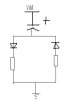
I am building a "scalable" capacitor array. I want to be able to use a dual dac (MAX519) to set the array charge and discharge rates. I was thinking of using both NPN and PNP darlington transistors to allow for different rates of charge. Can anyone point me in the right direction ?? I can't seem to get such a thing working.
CheerZ,
JB
")
