Continue to Site

Welcome to our site!

Electro Tech is an online community (with over 170,000 members) who enjoy talking about and building electronic circuits, projects and gadgets. To participate you need to register. Registration is free. Click here to register now.

  • Welcome to our site! Electro Tech is an online community (with over 170,000 members) who enjoy talking about and building electronic circuits, projects and gadgets. To participate you need to register. Registration is free. Click here to register now.

CANT UNDERSTAND THIS CIRCUIT HELPPP PLSS!!

Status
Not open for further replies.

cyprio7

New Member
hi guys. im new to electronics so please bare with my dumbness. I have to know how the rectification circuits in the attatchment iv enclosed work. Iv stared at the schematics for ages but im confused. Please would somebody explain to me the overall operation of these 2 small circuits, like what resistors the currents pass thru, where it gets clipped, wat is happening etc. Iv looked in loads of text books as well to help me but im stuck. pls help.

[/img]
 

Attachments

  • rectification_circuits.jpg
    rectification_circuits.jpg
    20.2 KB · Views: 471
  • rectification_circuits.jpg
    rectification_circuits.jpg
    20.2 KB · Views: 477
Vin = input
Vout = Output

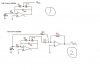
It seems with your half-wave rectifier, that you are depending on the diodes reverse break-down voltage to help you out. Without using Zener diodes (or equivalent), there is a 99% chance that the signal at the output of the opamp (operational amplifier) (point 6) will NOT go to Vout, unless Rf is a ridiculously small value, which in that case will make your "rectifier" just a plain resistor.

Because the non-inverting input (pin 3) is connected to ground, this amplifier runs as an inverting amplifier.

I think it is better to replace the diode connected between pins 6 and 3 with a resistor of at least 100K.

As for your full-wave rectifier, I think R5 can be omitted.

opamps tend to provide a ridiculous (I think) amount of gain, so you may get away with high or infinite feedback resistors.

that circle on the left represents the output provided from the last circuit.

There are others here that dealt with opamps more than me that can help you further.
 
No - I think on this occasion he is asking how the circuit works - he's not asking for maths or specific values. He has tried some research and given us the pictures.... help him out and share your knowledge.... :-D

Mike
 
MStechca,
The circuits are "classic" opamp precision rectifier circuits.
They use the open loop gain of about 200,000 of the opamp to effectively reduce the 0.6V forward bias voltage of the rectifier diode to nearly nothing, since the rectifier diode is inside the negative feedback loop.

Notice that the output of the halfwave rectifier circuit is not at the output of the opamp. It is at the junction of the rectifier diode and the negative feedback resistor so when the input voltage passes slightly past zero volts, the diode's output does the same in the inverted direction. A "perfect" rectifier with hardly any voltage drop.

R5 in the fullwave rectifier circuit can't be removed because it is very important for it to add the opposite polarity to the output summing opamp, making its output fullwave.

I don't have time now to discuss the function of all its parts, these circuits are all over the web.
 
hm this is the sort of situation where a nice electronics manual is realy handy (that i have not). maybe a good textbook will explain. i pressume books are still in use. i remember little of op amp configurations apart from the usual inverting and non inverting. for anything else i have to go check up.
 
Full explanations about how they work:

Precision half-wave rectifier: **broken link removed**

Precision full-wave rectifier: **broken link removed**
 
Status
Not open for further replies.

Latest threads

New Articles From Microcontroller Tips

Back
Top