Continue to Site

Welcome to our site!

Electro Tech is an online community (with over 170,000 members) who enjoy talking about and building electronic circuits, projects and gadgets. To participate you need to register. Registration is free. Click here to register now.

  • Welcome to our site! Electro Tech is an online community (with over 170,000 members) who enjoy talking about and building electronic circuits, projects and gadgets. To participate you need to register. Registration is free. Click here to register now.

Can you help for Current Step Up?

Status
Not open for further replies.

Rexkh

New Member
Hi Dear all

This circuit convert AC to DC. Output is supposed to be 5V 1A but it is only 130mA. Is there any piece I can replace to increase Amperage(Current)?

5V2A.jpg
 

Attachments

  • 5V2A.jpg
    5V2A.jpg
    512.2 KB · Views: 117
You do realize that the current is drawn by the device. Change the device for a 5Ω resistor and measure the current again or even the voltage.

Mike.
Edit, if the device is a 40Ω resistor then your supply is working correctly.
 
The device need 5V and 2A to work properly. There is nothing to do with the device because the problem is the adapter. Can't we just work on the circuit?
 
Your device needs 2A and you wonder why a 1A supply isn't working!!!

Edit, in case it isn't clear, the part you need to replace is the power supply.
 
The device work with 2A but it still work with 1A. That's not the point anyway. I just want to increase the current in this circuit. Is it possible?
 
If you change the transformer, voltage regulator, capacitors and resistors you might get 2A.

Mike.
 
Can you draw in my picture? Which one is transformer, voltage regulator, capacitors and resistors? This circuit is quite simple to start with.
 
This is the age-old USB "I want my phone to charge faster" gig...
 
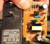
I see the resistor in the AC side. If I replace it with a smaller one, would it give more current to DC side?
No. That is most likely part of the circuit that limits the current on the input side. The limit is there because the transformer has been designed down to a price and will saturate only just above whatever input current is needed to get 1 A out. So if you increase the current, you will just get the transformer saturating, and it won't be transferring any more power, but everything will get a lot hotter.

That is a cheap, mass produced, switch-mode power supply. All the components are chosen to be as cheap as possible, so they won't have any spare capacity if it costs any money at all. In particular, the transformer will be designed for that application specifically.

Switch-mode power supply design is very complicated. It too hard for most of the contributors to this forum, including those who have years of electronics experience. A change from 1 A to 2 A would certainly need the transformer and the capacitors changing, but the transformer has been custom-made, so there is no simple alternative that would work or would be obtainable.

The alternative of buying the right sort of power supply is so much easier, cheaper, more reliable and safer.

**broken link removed**
$2.05 including shipping from China.

Newark have these:-https://www.newark.com/pro-elec/28-19338/adaptor-ac-dc-5-1v-2-5a/dp/15AC7490 for a bit more money but you can get it sooner. (They have over 42,000 of that particular one in stock, so they must sell lots)
 
I checked the capacitor. AC side is 4.7uf 400V and DC side is 470uf 16V. Do you think we can change one of them make get job done? On the other hand, can you tell me what are they on my mark on the picture below?
5V2A01.jpg
 
Changing the capacitors won't increase the current available. It would reduce the ripple a bit. You need to change the transformer, which is extremely difficult and time-consuming.

I still don't understand why you are attempting this when the alternative of buying the correct item is so easy.

The 4.7 μF capacitor on the input side seems too small for the 1 A rating, which goes to show how cheaply the power supply is made. The power rating of the power supply is 5 W, so on 110 V that is at least 45 mA. The input capacitor has to support the output for at least half the time, so on a 60 Hz supply, full wave rectified, that is for at least 1/240 seconds, or around 4 ms. A 4.7 μF capacitor, that is discharging at 45 mA, will drop by about 40 V in 4 ms, which is probably too much for the rest of the circuit to remain working, and 45 mA of ripple is too much current for a capacitor of that size.

To explain the components, 1 is an opto-isolator.

2 is a transistor, labelled Q2. I don't know what it does as I don't know what the circuit is. I guess that is turned on by the voltage across the big resistor, to and that Q2 will then turn off the big transistor.

I don't know what 3 is. I guess a fuse.
 
Status
Not open for further replies.

Latest threads

New Articles From Microcontroller Tips

Back
Top