Continue to Site

Welcome to our site!

Electro Tech is an online community (with over 170,000 members) who enjoy talking about and building electronic circuits, projects and gadgets. To participate you need to register. Registration is free. Click here to register now.

  • Welcome to our site! Electro Tech is an online community (with over 170,000 members) who enjoy talking about and building electronic circuits, projects and gadgets. To participate you need to register. Registration is free. Click here to register now.

Can this be done with just a single OpAmp and resistors?

Status
Not open for further replies.

dinofx

New Member
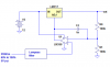
I'm going to use PWM to control the feedback pin to an LM317. I need to vary output voltage from 6 to 10 linearly based on duty cycle, so the control pin voltage needs to range roughly from 5 to 9 volts.

So, I have a square wave between 0 and +5 volts. I need the square wave boosted to +5 and +9 (let's say). I'm going to run the output through an RC filter to get a stable signal between 5 and 9 volts, which will then feed into the control pin.

I have a 12VDC power supply for the entire circuit.

Can this be done with on 741, some resistors and possible a pair of diodes? Thanks for your ideas.
 
Ok, how do I get linear output from a power transistor? I thought they were desigend to be completely on or off. I know I could create an asynchronous buck converter, but is there some other option?

The other problem I have is that I have an n-channel mosfet (IRF510). Doesn't this imply that I have to use it on the "low side", meaning vary the load's ground? It is important that the motors ground actually be the real ground, so that its tachometer signal is correct.
 
dinofx said:
Ok, how do I get linear output from a power transistor? I thought they were desigend to be completely on or off.

No, a transistor is an analogue device (either bipolar or FET), it 'can' be used as a switch, but it's essentially an analogue device.

The other problem I have is that I have an n-channel mosfet (IRF510). Doesn't this imply that I have to use it on the "low side", meaning vary the load's ground? It is important that the motors ground actually be the real ground, so that its tachometer signal is correct.

I'm not a big FET user!, personally I'd use an NPN emitter follower, with the emitter feeding the motor - the emitter will track 0.7V lower than the base voltage.
 
Ok, let's say I use a power transistor. I found something at radio shack called a TIP31. I'm attaching a new design. The problem I'm having is that the power transistor requires a significant amount of current going into the gate to allow 1 AMP to travel through it. If I add an additional transistor to help power it, I lose 0.7 volts twice. If I don't add a second transistor, I'm maxing out the current for the 741. Also, lower resistance means I need a larger capacitor to filter the PWM, so the amount of current being switched in and out of the capacitor is 10 times my LM317 circuit. Is this a significant amount of RFI?
 

Attachments

  • design.gif
    design.gif
    6.6 KB · Views: 446
Why do you want to run varying DC to the motor? Why not just PWM the +12V?
 
Ron H said:
Why do you want to run varying DC to the motor? Why not just PWM the +12V?

Two reasons. When the motor has no voltage, it would not report its RPMs correctly. The other reason is that if I pulse the motor 50% duty, it will just draw twice as much current half the time. It has a capacitor inside it that would basically enable it to run at 12 volts even when the pulse if off. There are other problems too.

I've modeled pulsing a load with a capacitor. If you don't have an inductor there, it is very hard to get any sort of smooth control of the load. But I really want to avoid pulsing 1 amp of current inside my computer even if it would work :)
 
You can put the LM317 inside the feedback loop, as below.
 

Attachments

  • pwm_to_linear.png
    pwm_to_linear.png
    9.6 KB · Views: 418
Thanks Ron, that's a nice idea. What software do you use?

I bet if I combine your idea of using the 317 as feedback, and my idea of boosting the input PWM by pulling in +12V, I can do the whole thing with only two resistors :) (edit: and of course a capacitor)
 

Attachments

  • pwmout.gif
    pwmout.gif
    15.1 KB · Views: 405
dinofx said:
Thanks Ron, that's a nice idea. What software do you use?

I bet if I combine your idea of using the 317 as feedback, and my idea of boosting the input PWM by pulling in +12V, I can do the whole thing with only two resistors :) (edit: and of course a capacitor)
I use Linear Technology's SwitcherCAD III.
Where is the LM317 in your schematic? Why do you want to pull the PWM up to +12V? Do you have control over the duty cycle range of your input?
OMG, I'm starting to sound like Walters! :D
 
LM317 control would be connected at the opamp's output.

The final step is to have the circuit operate differently when the tachometer is producing no output.

The tach generates brief pulses. Until these pulses start, I would want the circuit to operate at max Vout.

Can anyone explain the following terms to me from Intel's specs. What does pulled up mean?

PWM Frequency: Target frequency 25 kHz, acceptable operational range 21 kHz to 28 kHz
Maximum voltage for logic low: VIL = 0.8 V
Absolute maximum current sourced: Imax = 5 mA (short circuit current)
Absolute maximum voltage level: VMax = 5.25 V (open circuit voltage)
This signal must be pulled up to a maximum of 5.25V within the fan.
Note: New fan designs are strongly encouraged to implement a 3.3V pull up for compatibility with
buffer design limits on Hardware Monitor Devices e.g. Super IO devices.

And again, pulled up:
Fan shall provide tachometer output signal with the following characteristics:
• Two pulses per revolution
• Open-collector or open-drain type output
• Motherboard will have a pull up to 12V, maximum 12.6V
[/quote]
 
Status
Not open for further replies.

Latest threads

New Articles From Microcontroller Tips

Back
Top