technogeek
New Member
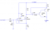
The circuit that was posted by Russelk here:
https://www.electro-tech-online.com/threads/adjustable-current-output.27691/
Can someone explain how it works? Maybe I just don't understand how the voltage regulator fits in to the big picture?
I think the fet works like a voltage controlled variable resistor to vary the current through the load... But I don't know where to begin to select part numbers for a specific "variable" constant current 1-100ma source.
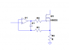