Electro Tech is an online community (with over 170,000 members) who enjoy talking about and building electronic circuits, projects and gadgets. To participate you need to register. Registration is free. Click here to register now.
Welcome to our site! Electro Tech is an online community (with over 170,000 members) who enjoy talking about and building electronic circuits, projects and gadgets. To participate you need to register. Registration is free. Click here to register now.
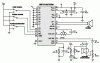
Me and my buddy wanted to make one of these out of scratch, could anyone draw me a schematic of it? I want to make use of all the buttons in my car that dont have a function. Here is the picture.
ok, from the picture you have given, it would take a phycic to work out how the circuit goes. If you had a picture of the other side of the circuit board, we might stand a chance.
However, IMHO, the chip looks like a microcontroller. This means that we would need to work out what code to program it with. This means we need to know what the circuit does.
If you have a picture of the other side of the board it would be very helpful, and if you could tell us what it does (in a reasonable ammount of detail), that would also be very helpful
Tim.
Edit: Sorry if I sound rude, but we really do need a bit more to go on, unless anyone happens to recognise the circuit in the photo, which isn't that likely.
P.S. is this a photos you have taken, or is it one you found on the net?
Going from the silkscreen legend on the board, I presume it's a voice recorder chip?. All you need to do is download the datasheet for it from the manufacturer - that should include a suitable circuit.
You were right, there is a schematic with the manual. This is for a voice recorder. My friend thought it would be cheaper to build it ourselves than to find one and buy it. We only need it to record 5 seconds or less instead of 40 seconds like the one pictured, but also be able to play the clip over and over. When building a voice recorder, do you need to program the chip? Maybe someone has a schematic of a voice recorder allready and wouldnt mind explaining it? We want to connect it to the car, so when the alarm is deactivated, it will say something. We havent thought of what exactly we want it to say... but we will figure something out. There are also alot of "ricers" in the area, and we also want to make a fake BOV. We would make a circuit that when a button is pushed it makes that sound of a BOV. It seems like another application of the voice recorder/player. Anyone with ideas/suggestions? thanks for the help
shuluke, I don't want to be rude either, but your question combined with the picture has some problems a schematic won't solve. You'd like to reverse engineer the product, right? The chip is a bucket-brigade type analog recorder/playback device. It may be an application specific device with a built-in microcontroller (meaning locked & hidden firmware). Unless you have a source for this specific part, forget it. (the rest of the components on the board are easy to find)
Digikey used to stock some inexpensive voice recorder/playback chips, but I didn't see any in their latest catalog. Maybe worth a search. Another option is an analog->digital => EPROM (storage) => digital -> analog circuit. It's more complicated, but can be made with commonly available parts (programming the EPROM can be a roadblock, though). I've seen these around on the web, and will post a link if I find one. The standalone voice recorder chips are a better choice, if you can find a source.
Its my 3rd year in Electrical engineering, and we were thinking of making some things to get better aquianted with electronics. Would it be better to just buy the the whole kit? I dont know how to program chips yet, that will be this fall semester in microprocessors. I am just trying to find things to keep me occupied and intrested in electronics. I have installed some things in my car, upgraded the sound system, worked with professional to wire alarm, built my own box for sub, and will wire it later this week. Any other ideas to do to a car?
another thought: if you are trying to make the circuit your selves (yes,it probably would be cheaper), then you are better off explinaing what you want it to do, and we will see if we can come up with some appropriate ideas for a circuit. If you want to build it yourselves, there doesn't seem much point in copying someone elses design...
for example, do you want it to be able to re-record things one in use, oris it just going to be used to playback the recorded noise?
In reality, it doesn't dump "excess boost pressure" -- what it does is prevents turbo slow-down when the throttle is closed for gear changes.
When you change gears with a standard transmission, the throttle closes as you release the accelerator and press the clutch. This causes a certain level of backpressure in the intake system, with air "flowing" back towards the turbocharger impeller wheel and slowing it down. When this happens, there is a momentary lag when you engage the next gear and accelerate as the turbo tries to spool back up. Having the BOV in place allows the back pressure to get dumped, which in turn tends to keep the turbo speed up.
Well really! shame on you "shuluke" why waste time and money trying to imitate when with a little thought a workable ( and practical) electric supercharger is within your grasp....
and I don't mean the bloody "E-Ram" !!!!
this news article from 2002....
European auto makers are encouraging Visteon Corp. to develop an electrically powered supercharging system that will improve performance of small engines. The supercharger is needed because internal combustion engine/electric hybrids — and the 42-volt systems that will power them — for the most part remain just out of reach.
Visteon engineers are working with customers on engine projects for 2005-2006 that will use the Visteon Torque Enhancement System, or VTES, with a 12/14-volt electrical system.
It would be easy to adapt the VTES system to a 36/42-volt system, says Visteon engineer Jeff Brown, but the costs and complexity of such systems mean manufacturers are sticking with 12/14-volt systems longer than was thought a few years ago.
And they are looking for ways to improve fuel efficiency to meet the coming 2008 European goal of 140 grams of CO2 per km, the equivalent of about 41 mpg (5.7L/100 km).
Visteon views VTES as a transitional system between today's engines and future gas or diesel/electric hybrid systems, but it predicts that hybrids will have less than 5% of the market in 2010.
The VTES system, as with a turbocharger, generates greater power by forcing more air into the combustion chamber. Traditionally, turbocharging has been the favored approach. But the problem is the annoying “turbo lag” that is inevitable, because the turbo compressor is powered by the exhaust gases.
In the VTES system, the compressor is powered by a brushless electric motor that turns an aluminum alloy compressor at 50,000 rpm — just 330 milliseconds after the driver demands acceleration.
Visteon has a dozen patents on aspects of its supercharger system, which has been in development for three years.
“We have patents on the motor, the application, electrical system management and the central interface, among others,” says a Visteon spokesman.
“The motor-compressor is about 30% of it, but integration is the difficult part. The competition might have a motor but not the integration.”
The motor requires 2kW of electric power in operation, so Visteon needs to manage the vehicle's entire electric network in order to stay within the limits of a 12/14-volt system.
Among other things, engineers packaged the battery next to the motor to reduce losses in the wiring and regulate output of the intelligent alternator. Boost pressure is 5.1 to 5.8 psi (0.35 to 0.4 bar), depending on the application.
To demonstrate the system, Visteon installed VTES in a naturally aspirated 1.2L Fiat Auto SpA engine and a 1.9L Renault SA turbodiesel. In the diesel, the airflow from the VTES is directed through the turbocharger, boosting the intake pressure faster than the turbo alone.
Ultimately, auto makers are interested in reducing the size of their engines if they can get the same performance, because fuel consumption will be lower. Reducing performance is not a marketable option.
Potential benefits are greatest in small- displacement engines. Brown says applications are impractical on engines larger than a 3L turbodiesel or a 2.3L naturally aspirated engine, because larger engines require more air than a 12-volt supercharger can deliver.
Thus, Visteon developed its program with Europe in mind, where engines are smaller than in the U.S. Most European car buyers express interest in enhancing performance, rather than downsizing, says Visteon, and there is more interest in enhancing turbodiesel engines than in boosting gasoline engines.
In a 1.9L diesel, torque is increased about 10% for engine speeds from 1,000 to 2,500 rpm, but there is some benefit even at top speed.
More dramatic results are possible with small gasoline engines. A 1.2L engine with the VTES system performs nearly as well as a 1.8L without VTES, yet fuel economy is 27% better.
Compared to a 1.2L engine without VTES, the more powerful VTES engine's fuel economy is unchanged at 39 mpg (6L/100 km).
“In everyday driving, you use only 30% of the torque available in your engine 90% of the time,” says Brown. “You pay a large penalty in fuel economy to have the extra power available that you rarely use.”
Compared to the 1.8L engine, drivers using a 1.2L VTES would save about $1,500 in fuel cost over 36,000 miles (58,000 km), with typical European fuel prices.
With the voice recorder, we wanted the car to say something when we disarm it. So maybe it only needs to be recorded once, then wired into the car alarm so when the car is disarmed it says "disarmed" or something. Or when you turn the car on, it says "welcome". I have a few buttons on my car alarm that i dont use, the remote start for example, that when i pushed that button, it will say "Protected by .... " or "Wecome" just something different. I think the best idea would be to go with something like a button.
I dont want to put this fake BOV on my car, but i know many who do. I dont mind working on something for them to enjoy, i mean its their car, ill let them do what they want. My cousin for example cant afford a turbo/supercharger but if i added this to his car, i bet he would be happy with it, performance or not. And to all the others who see it on my cousins car and ask for one, i dont mind getting paid a little to do it for them as well. As for the design as a whole, i was thinking of putting a button on the bottom of the gas pedal, so when fully depressed, the car is pushed and when let go to switch gears, it would release the button and the "BOV" would sound off, or in this case, the voice recorder would play. I could use a siren of a car alarm to make the noise, i was just wondering about this sound recorder... I would probably power it from the car battery as well.
On the picture i see the original chip from International Storage Devices (ISD). Today ISD formerly Winbond. ISD1016 the most cheaper version of family with 16sec record capability.
Just got a look at the photo ... the chip in question is made by Information Storage Devices (ISD) and it's part number is ISD2540P.
Here's a link to a datasheet I found at www.datasheetarchive.com: **broken link removed**
This datasheet should tell you everything you need to know about using this chip. JB
This site uses cookies to help personalise content, tailor your experience and to keep you logged in if you register.
By continuing to use this site, you are consenting to our use of cookies.