Dan Kuschill
New Member
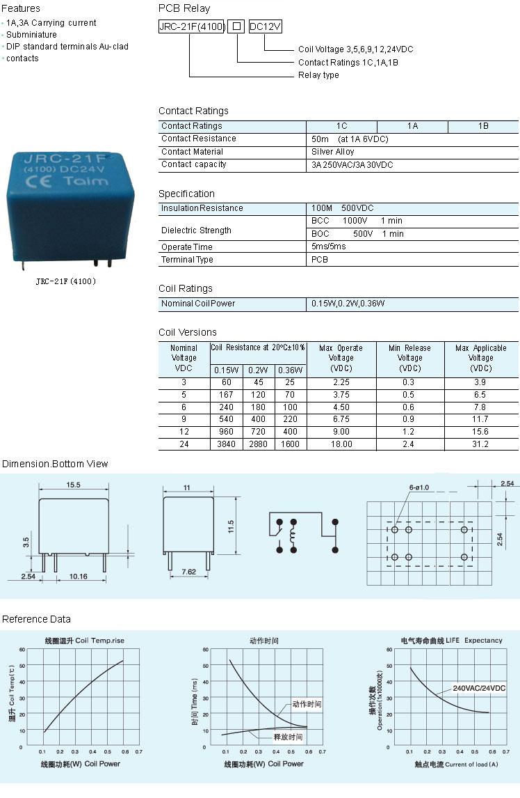
I am using a JRC-21F 4100 relay. The electricity I am using for the coil may be 5 volt DC or may be 12 volt DC. If I use a relay that is rated at 5V for the coil, I have noticed that either 5V or 12V will activate it. My question is if I use a JRC-21F 4100 5 volts, can I run 12 volts though it will no long term problems? I am just asking about the coil part.
Thanks
Thanks
")
