Electro Tech is an online community (with over 170,000 members) who enjoy talking about and building electronic circuits, projects and gadgets. To participate you need to register. Registration is free. Click here to register now.
Welcome to our site! Electro Tech is an online community (with over 170,000 members) who enjoy talking about and building electronic circuits, projects and gadgets. To participate you need to register. Registration is free. Click here to register now.
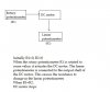
This is a flow chart that someone sketched for me, but is this feasible?
Also, can someone explain to me the working of the circuit in a simple manner.
I'm from a mechanical background, so my knowledge of circuits is limited.
P.S: I'm not looking for alternatives, my query is with reference to this specific question
It's called a servo - they are commonly used in radio control models, where the link between the pot and the servo is via the radio link, as a variable width pulse.
For local operation, you just need an opamp as a comparator, along with suitable bi-directional drivers for the motor - the monitoring potentiometer needs to be fed from a substantial reduction gearbox.
"For local operation, you just need an opamp as a comparator, along with suitable bi-directional drivers for the motor"
Could you explain it to me in a bit more simple manner?
Also, a servo has a 180 degree limitation right w.r.t the rotation of the motor?
My requirement states that the motor should rotate more than this
You can use a "POWER OpAMP", like a **broken link removed**. You will need split supplies. It will drive a DC motor directly. Position feedback could come from a potentiometer coupled to the motor shaft.
At the risk of annoying you further, could you sketch out the circuit to make it easier for me to understand?
Trust me, I really appreciate the effort taken by you.
You can use a "POWER OpAMP", like a **broken link removed**. You will need split supplies. It will drive a DC motor directly. Position feedback could come from a potentiometer coupled to the motor shaft.
No, I am assuming you want a create a motor drive voltage/current which is proportional to an amplified error term = (actual position - commanded position), so as to drive the motor to null the error term. That is, by definition, a Proportional POSITION SERVO. The OpAmp is set up to subtract the (Actual Position) from the (Commanded Position), amplify the difference, and supply the operating voltage/current to the motor.
Be advised that a simple proportional servo controller is usually not considered optimal for position control because it is marginally stable, and always leaves some residual error. The better way is to use a PID (Proportional Integral Differential) Controller, where the OpAmp I referenced above can be used as the motor driver, but requires a lot more stuff upstream. Google "PID control"
Thanks a ton Mike!
I looked it up just now, why does the configuration look similiar to that of your normal OP-AMP with a negative fedback?
Lol..Or is it because I'm a mechanical engineer? mackys: Making a PID controller out of an op-amp.
The reference you linked to is not quite a PID. It has a Differential term (C1), it has an Integral term (C2), but is lacking a Proportional term (no DC feedback). Most position servos require P and I, D is optional.
This site uses cookies to help personalise content, tailor your experience and to keep you logged in if you register.
By continuing to use this site, you are consenting to our use of cookies.
")