Continue to Site

Welcome to our site!

Electro Tech is an online community (with over 170,000 members) who enjoy talking about and building electronic circuits, projects and gadgets. To participate you need to register. Registration is free. Click here to register now.

  • Welcome to our site! Electro Tech is an online community (with over 170,000 members) who enjoy talking about and building electronic circuits, projects and gadgets. To participate you need to register. Registration is free. Click here to register now.

cadence flashing light for a bicycle spinning class

Status
Not open for further replies.

rhrotolo1950

New Member
My friend is a bicycle spinning instructor. This is an exercise class using indoor stationary bikes. The instructor tries to get everyone to pedal at a certain cadence. For example, 60 rpm, so she has to yell it out after checking with a stop watch.

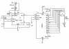
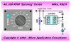
I am a Mechanical Engineer, but know little about circuits. I would like to build her a simple device, that she could dial in a certain cadence ( the range would be 40 to 100 rpm) and have a bright LED flash to that cadence. The power would be a 9 volt battery or other available battery. It would hang on her instructor bike, so every one could easily see the flashing LED and match their cadence to that.

I tried to google this but found circuits that were way past my level of understanding. I have a electronic stop watch that has this cadence feature, but no flashing light. Maybe there is a way to tap into that and insert a LED somehow.

Your help is really appreciated.

Thank you
Bob
 
An astable 555 will do this for you. You'll use the ouput to drive the LED directly or through a transistor depending on it's current requirements. Do you have any specs on the LED you're planning on using? I can post a schematic for you if you'd like.

Here's some info on the 555:

**broken link removed**
 
Last edited:
If you want accuracy then a divide by 10 rotary dial would be the ticket using a 4017
will try and get you something drawn up.
 
here you go should work

adjust the pot for 100 hz (100rpm) I made a mistake on the clock output. The values are for 100HZ at 50% duty cycle.
You need 3600hz? (its late and I gots to go to bed but with the right clock for 100 pulses per miniute then the 4017 just divides it by selector switch up to divide by 10
 

Attachments

  • cycle cadence..PNG
    cycle cadence..PNG
    35.1 KB · Views: 430
uhhhh, 100 hz isn't 100rpm.

555 circuit shown is adjustable from about 75 Hz to a few kHz. To get 60 pulses per minute, you would set the rotary switch to Q6 (divide by128) and fine tune with the pot.
 
It was past my bed time. Us old fogies need our sleep.
I realized when posting I used the wrong component values and couldn't think of what 100 high outputs is frequency wise?
If you set the selector switch to the divide by 10 position then adjust the pot for 10 flashes per min.. The rest will take care of itself.
Position one will be 100 flashes per miniute. Easier to count to 10 in one miniute than 100 in one min.
One dosen't even need ten positions, just what ever is needed..
 
metronome , in music, originally pyramid-shaped clockwork mechanism to indicate the exact tempo in which a work is to be performed. It has a double pendulum whose pace can be altered by sliding the upper weight up or down. The sliding bob indicates the rate of oscillation by means of calibrations on the pendulum. A number to indicate the rate at which the metronome is to be set and a note whose value is to equal one beat of the metronome are often given on a piece of music, preceded by the initials MM, for Mälzel's Metronome—Johann Mälzel (1772-1838) having made in 1816 the type of metronome in general use today. Beethoven and Schumann left such tempo indications for many of their compositions, but for earlier music and often for later music such indications are those of the editor. A pocket-watch type of metronome was developed in the 1940s; a boxlike electric metronome has also become popular, as well as digital metronomes.
 

Attachments

  • Image1..jpg
    Image1..jpg
    9.8 KB · Views: 210
adjust the pot for 100 hz (100rpm) I made a mistake on the clock output. The values are for 100HZ at 50% duty cycle.
You need 3600hz? (its late and I gots to go to bed but with the right clock for 100 pulses per miniute then the 4017 just divides it by selector switch up to divide by 10

I think for this to work you would have to also connect the reset pin of the 4017 to the common connection of the rotary switch. As it's drawn right now, changing the rotary switch won't change the frequency at which the LED is blinks. Or am I missing something?
 
Just found this kit and thought it could work for you.

**broken link removed**

All you'd have to do it leave out one of the LEDs. With the component values that come in the kit, the flashing will be adjustable from ~.6 hz (36 rpm) to ~4.8 hz (288 rpm). You can increase or decrease the range of rpm by changing the values of R2 and/or the 100 kΩ pot. It would also probably be a good idea to replace the pot that comes in the kit with a panel mounted one so the output frequency can be adjusted without having to whip out a screwdriver.
 
A range of 10 to 100 RPM is only 0.167 to 1.667 revolutions per second (Hertz). Generating a square wave output to drive an LED for periods that long is easy using a $2 microcontroller running a simple DDS (direct digital synthesis) algorithm (no waveform table required).

Choose a DDS phase width and sample frequency that allows using the "rpm" variable directly as the DDS frequency phase offset. Read a pot' periodically in the main program and use the upper 8-bit ADC result divided by 2, plus 10, and use that value to set the "rpm" variable to 10..137. The ISR (interrupt service routine) generates the LED square wave output in the background.

You'll need to use a frequency counter or a stopwatch to mark tertiary scale lines on the dial for values between the 10 and 137 rpm ends of the pot'.

Regards, Mike

Code:
unsigned int accu = 0;         // phase accumulator
unsigned int rpm = 10;         // rpm, 10..137

//
//  the entire DDS "RPM" software engine
//
void interrupt()               // 920-usec (1086.96-Hz) interrupts
{ pir1.TMR2IF = 0;             // clear timer 2 interrupt flag
  accu += rpm;                 // bump phase accumulator
  if(accu.15)                  // if hi portion of square wave
    GPIO.2 = 1;                // set LED output hi
  else                         // if lo portion of square wave
    GPIO.2 = 0;                // set LED output lo
}
 
Last edited:
OUPS the resetpin is connected to the R8/rotary switch connection.
using the 4017 you can get a defined pulse rate but only divisable by ten (10,20,30,40 etc.)
 
OUPS the resetpin is connected to the R8/rotary switch connection.
using the 4017 you can get a defined pulse rate but only divisable by ten (10,20,30,40 etc.)

If the rotary switch is set on Q1 for example, then the LED will turn on and the 4017 will get reset every 2nd clock pulse from the 555. If the rotary switch is set on Q4, it will be every 5th clock pulse and Q9, every 10th clock pulse. So, the frequency of the square wave output as seen by the LED is equal the 555 frequency divided by 1,2,3...10 depending on what output the rotary is connected to. The LED on time will be the same regardless of which output of the 4017 it is connected to and it will be equal to the high time of the 555 clock pulse. Changing the rotary switch position will vary the frequency and duty cycle of the LED pulsing but will not change the on time.
 
if the clock pulse is 10hz (10 pulses per second) and the rotary switch is on the Q9 output then the LED won't light until after 9 pulses. so the LED will flash once every second in theroy. So basically you have divided ten pulses into 1 pulse per second.
The reset pin is connected to the Q9 output so the switch has only 9 positions instead of 10.
Its a count to X and recycle.
 
better explanation

here is a count to X circuit. The LED is connected via a rotary switch.
 

Attachments

  • 4017 circuit..PNG
    4017 circuit..PNG
    85.5 KB · Views: 240
Here's my solution based on a $1.41 PIC 12F683 microcontroller (Mouser.com, single quantity) running the simple DDS program I mentioned in my previous post.

If you can still find potentiometers with built-in switches then you could use the switch for on/off power control. I suspect it could be battery powered without too much trouble too.

Regards, Mike
**broken link removed**
<added>

I'm sure you could use a 55 cent 6-pin 10F' PIC instead of the 8-pin 12F' PIC for this project/product too but the DDS program would be a bit more work and not nearly as simple and elegant.
**broken link removed**
 

Attachments

  • Spinning Strobe..PNG
    Spinning Strobe..PNG
    21.4 KB · Views: 208
Last edited:
will a Junebug program the 12F683
If so perhaps I should be learning assembly instead of Swordfish??
 
will a Junebug program the 12F683
Yes.
If so perhaps I should be learning assembly instead of Swordfish??
Swordfish BASIC is an excellent compiler but it limits you to the 18F' devices. Assembler isn't necessarily the best language in all situations either.

I recommend learning C which is a bit more "mainstream" compared to BASIC.

I use the free/lite version of Sourceboost BoostC in MPLAB IDE (instead of the Sourceboost IDE) for 12F' and 16F' projects or Microchip MCC18 in MPLAB for 18F' projects.

Kind regards, Mike
 
Last edited:
An astable 555 will do this for you. You'll use the ouput to drive the LED directly or through a transistor depending on it's current requirements. Do you have any specs on the LED you're planning on using? I can post a schematic for you if you'd like.

Here's some info on the 555:

**broken link removed**

Thank you for your help. I have no clue as to which LED to use. A schematic would be great. Thanks again
 
Thank you for your help. I have no clue as to which LED to use. A schematic would be great. Thanks again

Did you see the kit that I linked to in post #9? That kit has everything in it for you to build what I was talking about in my reply that you qouted. There is even a schematic on the web page. There is one thing that I realized about the idea since I posted it though. The duty cycle of the LED will remain around %50 - %60 regardless of the setting. So, when the cadence is set at a slow pace, the LED will stay on for longer instead of just blinking. I'm not sure if that's somehting you care about or not. If you do, I can post instructions for you on how to modify the kit to produce a more desirable output.
 
Status
Not open for further replies.

Latest threads

Back
Top