Increazon
New Member
Hello. I trying to findout how to calculate Common Emmiter Amplifier.
When i simulating board, i get unexpected distorts of signal.
Ok. I built this scheme -> NPN Common Emitter Amplifiers
Now look at pics.
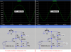
This is with bypass emiter capasitor, range can be from 5 to ∞ µF, same result.
**broken link removed**
This is oscilogram
**broken link removed**
As you see - bad work of amplifier
Now lets remove capasitor
**broken link removed**
And look at oscilograme
**broken link removed**
Its just ideal! What we need.
More info. This Simulation - in Altium designer, also i check in Multisim and Proteus - same result!
When i simulating board, i get unexpected distorts of signal.
Ok. I built this scheme -> NPN Common Emitter Amplifiers
Now look at pics.
This is with bypass emiter capasitor, range can be from 5 to ∞ µF, same result.
**broken link removed**
This is oscilogram
**broken link removed**
As you see - bad work of amplifier
Now lets remove capasitor
**broken link removed**
And look at oscilograme
**broken link removed**
Its just ideal! What we need.
More info. This Simulation - in Altium designer, also i check in Multisim and Proteus - same result!
- Why this happens?
- Why we need this capasitor?
- What right equation to calculate this capasitor?
")