Continue to Site

Welcome to our site!

Electro Tech is an online community (with over 170,000 members) who enjoy talking about and building electronic circuits, projects and gadgets. To participate you need to register. Registration is free. Click here to register now.

  • Welcome to our site! Electro Tech is an online community (with over 170,000 members) who enjoy talking about and building electronic circuits, projects and gadgets. To participate you need to register. Registration is free. Click here to register now.

Building lt spice transformer / help!

Status
Not open for further replies.
Well if you look at the Transformer physically. You see from Left to right each winding 1,2,3,4 if I'm going to center tap, which windings will I bring together? to get the nessessary result for my Secondary.

Edit: Of course this is the Transformer going into my Plasma Speaker Circuit.
 
Basically, which are primary's in the real world and which become secondary? or can I pick any winding and output it to it's corisponding points in the circuit, which will conduct according to load?

Which indicates, if true, then the loads or end points, will determine L1, L2,L3,L4 and not how they lay on the Transformer to determine how they are numbered.

As you can see I'm a Tech and not a designer. I work with Manuals, which are pre-determined Voltages and not how the inner working, work together. Thats why I'm here.

I've alway been confused about that. Just, what are their relationships?

Edit: Out of my own mind, I say hook up any winding, with respect to their I/O (Input and Output) and go with it. But, then I say, no, you must know, the relationship is before moving on!
 
Last edited:
Ideally, each winding is identical to the others and it shouldn't matter which winding is used as a primary, or as a secondary.

For maximum coupling efficiency, a four winding transformer should be wound "quad-filar." Meaning that you start with four wires and wind them together around the core. So going around the core you would have ABCD.ABCD.ABCD etc. 14 times.

Note: This assumes that the voltage rating of the wire can withstand the applied winding to winding voltage stress. If the windings will see more than a couple hundred volts, then special magnet wire is used with a high voltage rating is used for one or more of the windings.
 
I did wind according the ABCD,ABCD,ABCD,ABCD so, as you say, I will find the corresponding points and be, Happy, Happy, Happy.

Thanks for reading into, how I frame my questions.

kv

I really owe you something, it would be cool if I can get it to work, and show it to you.

Thank you.
 
Last edited:
Ok, I hope I did this right. Check it for error.
 

Attachments

  • My first LT Spice Drawing final.asc
    4.6 KB · Views: 286
I don't have a symbol for the SG3525, so I can't check those connections, but C1 and C2 will block the current that needs to flow in the two sides of the primary. They would be needed if the outputs of the SG3525 were current sourcing/sinking. But since they sink current only, they need to be DC coupled to the transformer windings.

The value for the four inductors should be the inductance of 900uHy.
 
900uHy can't be input in the Spice (Edit Transformer winding) etc. Showing

Inductance, series resistance, parellel resistance.

Or can I use 900uHy?


I will remove C1, and C2. But, just to be clear on the value of the inductors, what should I use for (H) in post #14 or how should it be written in a Spice model .999 maybe?

kv
 
Last edited:
Here is the .rar file of the SG3525 sent to me.
 

Attachments

  • SG3525A.rar
    2.2 KB · Views: 282
I just noticed I put K1 L1 L3 L4 .995 instead of .999 or .99

I just change it.
 

Attachments

  • My first LT Spice Drawing final.asc
    4.6 KB · Views: 270
Looking over the Schematic I named the coils wrong, it should be correct now. L2 and L3 were not correct.
 

Attachments

  • My first LT Spice Drawing final.asc
    4.6 KB · Views: 270
The 10,000uF caps; you have the value and name reversed.
Need a voltage source or two.
FET2 gate drive transformer not connected.
RT goes to gnd.
CT goes to gnd.
I do not understand why the OSC is not working. It has been 10 years and my memory is bad.
It looks like you want to make a class D audio amplifier.
Go find a power supply design that works. Connect the OSC and soft start parts correctly.
Your OUTA and OUTB are strange. You should not short A and B together.
 

Attachments

  • spice.png
    spice.png
    12.3 KB · Views: 678
So, I used 900u and kept .995 in, I removed C1 and C2.
 

Attachments

  • My first LT Spice Drawing ETO.asc
    4.3 KB · Views: 263
Last edited:
Too late here. Need to be on the road in 7 hours.

Thanks Ron, Safe Trip. I just want to prove this original schematic to work or not, and if I can salvage it or not.

To many people have tried it and failed and not said anything, the Author continues to get hits without just deserve. (He's fooling people)

I have to go to.
 
your still funny, having fun at my expense. I know you will deny it
Certainly I deny it. I was merely trying to get clarification from you. 'u' could have referred either to 'micro', or to the core permeability coefficient. And, like Ronsimpson in post #5, I was unsure whether you were trying to build or just simulate a transformer.
 
Certainly I deny it. I was merely trying to get clarification from you. 'u' could have referred either to 'micro', or to the core permeability coefficient. And, like Ronsimpson in post #5, I was unsure whether you were trying to build or just simulate a transformer.

Ya, I should have communicated it better, luckily, Chris understood me he's been helping me out a lot. I do want to build this, but the first one I built from the instructables website didn't work. Chris suggested trying a center tap on my transformer, thats when I thought maybe I really should first try to simulate it.

I already rapped another Transformer, but stopped doing anything until I can get a handle on this thing.

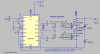
Have a look, the original Schematic and Claim https://www.instructables.com/id/A-reliable-plasma-speaker/

I believed in the beginning that this circuit would be ok to build for a guy like me. Trusting the Instructables website. I spent all 8 day's of my time off working on one "dam" board, only to find that it wouldn't work the way Author Claims. I would like to challenge that claim, I have followed intelligent engineers working on Developmental Projects as a Tech and held a position as a QC and QA agent, with the Largest Shooting Range Company in the World. I'm not a complete idiot, but I don't want to be made a fool or allow others to suffer this expense.

But, the truth maybe that it's all to generate hits for both sites and I was duped. I then found a few people, including a Member on AAC who tried to build it, and because of time, he couldn't continue or he would have found fault with it, and maybe mention it to Instructables.

I'm willing to continue until it's proven to be a faulty circuit or not. If it's Faulty, I want instructables to pull it from their site and make the Author stand up for his claim.

Thank you for leading me to LT Spice. Maybe I should sim the first schematic he posted too!

I just want to stop the Madness, either he's a Genus or a Fraud.

kv
 
Last edited:
You're not the first to complain about non-workable circuits on that site :D.
 
u in LTSpice is the abbreviation for 1e-6, just like m is for 1e-3 and n is for 1e-9. If you want 1e6, you have to write it as Meg or meg.

The inductance of an inductor could be 0.0000013 or 1.3e-6 or 1.3u or 1.3uH (in the last case, the H is actually ignored)

As to your other questions, look at this

I've been here ........http://eecs.oregonstate.edu/education/docs/ece323/Appendix.pdf

I get it.

Your core has an Al value of 4620nH
14 turns ^2 = 196

196 * 4620^-9 = ~900uHy for each of your 4 windings.

Add a spice directive (like alec_t said in post #2) of "K1 L1 L2 L3 L4 .995"

The number at the end is the coupling efficiency. 1 implies 100%. A more practical value would be .99 to .995

If you have more than one transformer in a circuit you would have more K directives.
K2 L5 L6 .995
K3 L7 L8 L9 .995
etc.

Series resistance is the DC resistance of the winding. It's not critical for your transformer, but put in 10 milliOhms as a rough estimate. Leave parallel resistance open.

Chris, I have been here. http://en.wikipedia.org/wiki/List_of_mathematical_symbols

I've still got a lot of math to do, I need to test out in the next year on Mat1010 and C programming in order to enter a class for Certification Network Security.

I'm re-learning my Maths at 56. This is helping so much, Thanks.

Remember I'm not a Pro, not in the least.

kv

Thanks
 
Last edited:
u in LTSpice is the abbreviation for 1e-6, just like m is for 1e-3 and n is for 1e-9. If you want 1e6, you have to write it as Meg or meg.

The inductance of an inductor could be 0.0000013 or 1.3e-6 or 1.3u or 1.3uH (in the last case, the H is actually ignored)

As to your other questions, look at this


I think I found the Inductance as

B=
0.003628192286234499 which is

3.628192286234499 mH How is inductance derived from this or is the result correct.

I went to...the calculator .... to answer my question the site ..... look at this...I'm not able to arrive at the inductance from these values, I'm not sure what to do next.
 
Last edited:
Status
Not open for further replies.

Latest threads

New Articles From Microcontroller Tips

Back
Top