Continue to Site

Welcome to our site!

Electro Tech is an online community (with over 170,000 members) who enjoy talking about and building electronic circuits, projects and gadgets. To participate you need to register. Registration is free. Click here to register now.

  • Welcome to our site! Electro Tech is an online community (with over 170,000 members) who enjoy talking about and building electronic circuits, projects and gadgets. To participate you need to register. Registration is free. Click here to register now.

Building an electronic quiz

Status
Not open for further replies.

kakabunny

New Member
Hi, i'm building an electronic quiz for my school project but i'm a little confused as to what to do.

I'm going to be making a quiz where there are questions displayed, and you have 2 levers for true and false. If you answer correct, green lights will flash (i'll be using 555 timers for that) and if you answer wrong red lights will flash. However I don't know how the machine will be able to know which questions are right and whitch ones are false (there are 10 questions that are going to be in order and they are labelled numerically so you have to do them in order). When you answer a question, you just remove it from the machine and go to the next one. How do i get the machine to recognize the answer to the question and display the correct lights? Is this anything related to programming chips or something? I'm confused:p

here is a pic of what i'm trying to do and a circuit diagram would be very very helpful, even if it's not detailed.:)

ImageShack - Image Hosting :: helpppp.png
 
PIC maybe but?

you would need to programmthe PIC but the ansewers could be memorized thus the person taking the quiz could get 10 out of 10 correct.
my first thought is have 10 DIP switches
ON = TRUE
OFF = FALSE
set switches in accordance with the questions
can then change the qestion order / as well as reset the DIP switches
an array of AND gates would do the trick.
if interested let me know


Thanks a lot man!! I know someone could memorise the questions but i just need to show that I can make this quiz for a good mark on my coursework:p

Definitely interested, thx again!!:)
 
do you want to keep track

of correct answers vers wrong answers?
only one pair of switches for "contestant"?
just 2 bulbs= red and green?
small LED's or light bulbs
a digital readout of correct vers wrong answers?
 
of correct answers vers wrong answers?
only one pair of switches for "contestant"?
just 2 bulbs= red and green?
small LED's or light bulbs
a digital readout of correct vers wrong answers?

Yes, i want to keep keep track of correct vs wrong
Yes just one pair of switches for a contestant (the questions will be ordered again, so the switches should be reset or something)
There will be more that 2 bulbs. 3 green ones and 3 red ones going down the side. (as in pic). They are LED's.

I haven't thought about a digital readout, i'm not sure how that works yet :p:eek:. Lets just leave it out, i'll just have a space on the quiz where you can tally answers:p

thxx a lot man!!:)

EDIT: I might make the levers connected to a linkage whitch then start the circuits, just mentioning it since it could be related
 
Last edited:
here is a start

just add 6 more key code switches (true false answers pre programed)
have one switch for the data entry switch but using a shift register or even a 4017, select each of 10 inputs to the 4070's using AND gates ??
YOU need to figure out the logic
YES this is doable
 
just add 6 more key code switches (true false answers pre programed)
have one switch for the data entry switch but using a shift register or even a 4017, select each of 10 inputs to the 4070's using AND gates ??
YOU need to figure out the logic
YES this is doable

thx for the start man. could you explain clearly how i can use that schematic for my circuit diagram?? So i have 10 key code switches and 1 shift register as the data entry switch. Then all the 10 key code switches connected to 10 4070's using AND gates???

thanks again
 
Her you go

This is enough to get your homework started.
you need to add more AND gates and dip switches.Don't forget the resistors on the dip switch/4070 as in the like I sent earlier.
you need a de-bounced monetary push button to clock the 4017. A 555 mono is easy and clean or use leftover gates.
then you need to draw up a truth table
oh yea I accept Paypal for doing your homework
 

Attachments

  • Capture4-18-2009-4.06.04 PM.jpg
    Capture4-18-2009-4.06.04 PM.jpg
    143.8 KB · Views: 198
This is enough to get your homework started.
you need to add more AND gates and dip switches.Don't forget the resistors on the dip switch/4070 as in the like I sent earlier.
you need a de-bounced monetary push button to clock the 4017. A 555 mono is easy and clean or use leftover gates.
then you need to draw up a truth table
oh yea I accept Paypal for doing your homework

thanks a lot man, i really really appreciate this :eek::p. im sorry man but i have no money to give you :( 
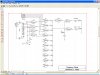
(unless u werent being serious :D)

but rly, thanks alot
 
I was just kidding

but now you need to finish it up.
FIRST draw up a truth table of each event-correct answer, wrong answer.
write down what each gate outputs. This WILL assist you in learning and if it doesn't work then why.
A simple logic pen comes in handy (an LED, a resistor and an alligator clip)
look up logic pen circuits. this will really help a lot. Sometimes simple is the best (less to go wrong).
Oh yea I want to see your truth tables just to see if you did your homework.
 
Procrastination gets you in deep Cah cah...
 
I have my doubts on this project

I gave KaKabun all the info that's need.
sure its way out in left field as far as number of gates but maybe, just maybe they will learn something about using logic gates
I myself am self taught (read-lots of reading and experimenting) not sure about a-lot of things but I plug along until I get it right
Hopefully KaKabun will build this circuit and come away with a sense of accomplishment
spending lots of time on learning how to program a PIC and build an actual product.
 
Status
Not open for further replies.

Latest threads

New Articles From Microcontroller Tips

Back
Top