Continue to Site

Welcome to our site!

Electro Tech is an online community (with over 170,000 members) who enjoy talking about and building electronic circuits, projects and gadgets. To participate you need to register. Registration is free. Click here to register now.

  • Welcome to our site! Electro Tech is an online community (with over 170,000 members) who enjoy talking about and building electronic circuits, projects and gadgets. To participate you need to register. Registration is free. Click here to register now.

Building a Power Supply, is it worth it for this project?

Status
Not open for further replies.

Wasre

New Member
Hi,
I'm relatively new to the forums, first post here, but I've been trolling through looking to see if I find an answer before posting. Sorry if this happens to be a redundant posting.

Here's the scenario:

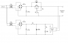
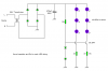
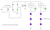
I'm looking to design a UV Exposure unit for PCB/Silk Screening using LEDs. I know the basics of what I want for power and LEDs. Based on my calculations I need 48Vdc for the LEDs including a 100Ω resistor for each series array.

While I've been reading a lot about power supply design, I'm wondering if it's even worth attempting to build my own power supply, or look for an off the shelf regulated power supply that will give the 48V I'm needing. (At least, I'm thinking I'm needing a regulated power supply.)

I figured I'd give this question first before inundating the forum with questions pertaining to building a power supply if it would be wiser/cheaper to purchase something pre-made. Granted I'd like to learn more about building a supply, but I'm still learning the intricacies based on what I've been reading.

I'm also looking to figure out a way to make the individual series arrays essentially modular so if one array flakes out, the entire unit doesn't have to be sent in for servicing. Unplug the faulty module, and replace it with a new one. The problem I'm running into is finding a solution like a buss system that is readily available without having to manufacture it by hand.

Any suggestions would be appreciated. Any links to information gladly accepted.
 
I'd just buy one. But I'm not a fan of building equipment in order to build things I'm interested in. ALmost always costs more in the end. ANd if you buy one that's good enough you could use it for things other than your Exposure unit.
 
Last edited:
How much current do you need?

How well regulated does it need to be?

If you want a basic unregulated supply, then just connect a 36VAC transformer (a transformer with a twin 18V secondary will do) to a bridge rectifier and a suitable filter capacitor.

If you need a regulated supply then it's a little more difficult, an LM317 can be used to regulate a higher voltage down to 48V so long as the voltage differential doesn't exceed 40V, 88V in total.
 
Well, considering the power will be for UV LEDs, I'm guessing that I don't want the voltage to fluctuate too much. Each LED has a Forward voltage of 3.3V and draws 20 mA. Each series will have 14 LEDs plus the 100Ω resistor. Then I'll be putting several of the 14 LED series units together in parallel. If I do 16 modules of the LEDs, the current draw is currently showing as 320mA with total power dissipation of 15.424W. 14 modules is 280mA and 13.496W dissipation.

Any idea how regulated/filtered/smoothed power really should be for LEDs? Once I get the arrays built, figure out my power distribution method (some form of a bus bar is what I'd like to make the array board pluggable), there will be a timer in the circuit for users to set their desired exposure time (I'd like to eventually make this a digital timer, but that will come later).

Again, thanks for the feedback.
 
Hey,

I built my own PSU awhile back, a linear design using the LM338 regulator. I think you could squeeze around 5A out of it, but even I haven't used that much current yet.

Take a look at the link below or a better description:

**broken link removed** - Courtesy of birdman0_o

Most importantly, have fun! ;)

Austin
 

Attachments

  • HomebrewPSU1..PNG
    HomebrewPSU1..PNG
    14 KB · Views: 193
Last edited:
Well, considering the power will be for UV LEDs, I'm guessing that I don't want the voltage to fluctuate too much. Each LED has a Forward voltage of 3.3V and draws 20 mA. Each series will have 14 LEDs plus the 100Ω resistor. Then I'll be putting several of the 14 LED series units together in parallel. If I do 16 modules of the LEDs, the current draw is currently showing as 320mA with total power dissipation of 15.424W. 14 modules is 280mA and 13.496W dissipation.

Any idea how regulated/filtered/smoothed power really should be for LEDs? Once I get the arrays built, figure out my power distribution method (some form of a bus bar is what I'd like to make the array board pluggable), there will be a timer in the circuit for users to set their desired exposure time (I'd like to eventually make this a digital timer, but that will come later).

Is 20mA the absolute maximum current rating or is it the recommended operating current?

You shouldn't run at the maximum rating continuously, because it will shorten the life.

Why not connect the LEDs in parallel, that way you can use a lower and more convenient voltage?

7 LEDs in series enables to use 24V which is more common but that doesn't leave you much headroom for the supply voltage or forward current to change much.

Another option is to use a constant current source. You can buy ready-made 300mA current sources for powering high powered LEDs. Alternatively you could make your own using an LM317 or a transistor.
 
Is 20mA the absolute maximum current rating or is it the recommended operating current?

20mA is the recommended forward current. I don't know the max off hand but some of the ratings having been listed for these particular LEDs did show statistics for use at 25mA as well. If I had to guess, I'd venture to say the max might be somewhere around 30mA.

Why not connect the LEDs in parallel, that way you can use a lower and more convenient voltage?

This is partly due to the planned dimensions of the exposure unit, the effective viewing angle of the LEDs (currently using 30 degree viewing angle LEDs) and the fact that the overall system will have more sets of the 14 LED arrays. My goal, if possible, will be to make the overall exposure unit user upgradeable by allowing the user to add more arrays or replace an array should something happen to it without having to send it somewhere for service or have to perform a lot of diagnostics/disassembly to figure out which LED is not functioning. A basic unit would start off with something along the lines of 7 or 8 of the arrays. Each array will end up being in parallel to the other. In the long run, the entire unit could eventually hold up to 18 - 20 of the arrays to give coverage for roughly 42x48" when fully populated.

7 LEDs in series enables to use 24V which is more common but that doesn't leave you much headroom for the supply voltage or forward current to change much.

I suppose I could use 7 LEDs if I could find the right viewing angle, but those might be hard to come by.

Another option is to use a constant current source. You can buy ready-made 300mA current sources for powering high powered LEDs. Alternatively you could make your own using an LM317 or a transistor.

Would this be something difficult to design and/or build? Ideally, this will be inside the enclosure with with a standard 3 prong grounded plug and fans to help draw out heat from the ends or sides.

I appreciate the input. Thanks!
 
Here's how I'd do it.

Use a transistor and a sense resistor for each LED string.

The current will be about 18mA per string of LEDs.

I haven't shown all the LEDs for simplicity's sake.
 

Attachments

  • UV LEDs..PNG
    UV LEDs..PNG
    2.9 KB · Views: 169
Here's how I'd do it.

Use a transistor and a sense resistor for each LED string.

The current will be about 18mA per string of LEDs.

I haven't shown all the LEDs for simplicity's sake.

That looks easy enough to do. So what are the Diode values that are immediately to the left of the LED strings? For the rectification, would most any full-wave bridge rectifier work so long as the PIV is rated high enough for the 44V coming off the transformer's secondary?

It appears to me in the schematic that the base of each transistor is connected. Is that correct? I'm not sure how I'd do that if each LED string is planned to be its own separate board with no electrical or mechanical connection to another string, aside from the connection to power and ground.

What I've envisioned, if it's even possible, is: a board 1.5 inches wide by 21 inches long, as an example (haven't settled completely on the viewing angle of the LEDs so length/width of the string module hasn't been finalized quite yet), completely self contained that would snap into some kind of power buss distribution system. I'm wanting to reduce where possible the total number of wires running through the housing box.

Thanks for the schematic and information
 
Yes, you can use any rectifier but remember the peak voltage is 44√2 = 62V so use one with a maximum voltage rating of 100V.

You could use an LM317L which is much simpler.

The disadvantage is it has a higher drop-out voltage but that shouln't matter here.

There 44V transformer needs to be rated to 20VA. Don't worry if you can't find a 44V transformer, you can use a transformer with twin 22V secondaries connected in series or twin 24V secondaries in series for 48V.

EDIT;
Schematic attached.
 

Attachments

  • UV LEDs LM317..PNG
    UV LEDs LM317..PNG
    2.9 KB · Views: 169
Last edited:
Ahh, so for best voltage regulation, the LM317L should be individually in series with each LED string? Am I reading that schematic right? That looks really easy to do. Thanks a lot for the suggestions! As a matter of curiosity, so I can make this a good education point instead of merely feeding off the work of others, what is the calculation for figuring out the Rs resistor value?

I'll look at putting this together this weekend on my Breadboard, at least the PSU portion or sourcing out the parts. The LEDs I already have, the rectifier and LM317L not a problem. The next part will be finding the transformer, but Google searches are looking ok so far. I have a couple decent electronics parts stores locally (not Rat Shack) that I can talk to about transformers, etc.

I'll keep you posted.
 
Ahh, so for best voltage regulation, the LM317L should be individually in series with each LED string? Am I reading that schematic right?
Yes, that's right.

That looks really easy to do. Thanks a lot for the suggestions! As a matter of curiosity, so I can make this a good education point instead of merely feeding off the work of others, what is the calculation for figuring out the Rs resistor value?
Sorry I've just realised I didn't label the pins.

**broken link removed**

Use Ohm's law, the voltage across the sense resistor is always 1.25V.

I = V/I = 1.25/0.02 = 62.5R, the nearest E12 value is 68R.

I'll look at putting this together this weekend on my Breadboard, at least the PSU portion or sourcing out the parts. The LEDs I already have, the rectifier and LM317L not a problem. The next part will be finding the transformer, but Google searches are looking ok so far. I have a couple decent electronics parts stores locally (not Rat Shack) that I can talk to about transformers, etc.

Just one word of warning: the LM317L is only rated to 40V.

This isn't a problem as the LEDs will drop 46V so the voltage across it will be within the rating.

The voltage on the filter capacitor will be 44√2 = 62V minus the rectifier losses, plus 10% to 20% is the current drawn is below the transformer's maximum rating.

In other words don't operate the LM317L with too few LEDs in series, otherwise its maximum voltage rating will be exceeded.
 
Ok, here's an update of where I am so far. I'm still working on finding a transformer at the ratings that I've previously stated. I have done some re-calculations on the number of LEDs based on the viewing angle of LEDs I currently have and the desired length of the board for the string. I may be able to reduce the number of LEDs if I extend the distance between the top of the LED and the platen. Haven't done enough testing to determine if this will give the desired results or not yet.

Since I'll be working with Mains voltage 120V / 60Hz, can you point me in the right direction so I can figure out the rating and type of fuse I should have on the Hot leg of the incoming power leads? In your last post, I'm not sure I understand what you're referring to for the 10% to 20% is the current drawn is below the transformer's maximum rating. Are you saying that the total current draw including Rectifier loss is at least 10% - 20% below the 20VA rating, or am I needing to look at Voltage across that circuit?

I understand the 44V is RMS and the 62V is peak. Does the Voltage drop across the rectifier vary much from one manufacturer to another? Will that information be listed in a Spec Sheet?

Thanks for the help so far.
 
The transformer's secondary voltage will be between 10% and 20% higher than the rated value when no load is connected.

The rectifier will normally drop about 0.6V per diode off load or 1V per diode at full load. There are two diodes in series in a bridge rectifier, so the total voltage drop varies between 1.2V and 2V. Different rectifiers do vary slightly, look at the data sheet if you're not sure.

As I said before, if you can't find a 44V transformer you can make a 48V transformer from a 24V transformer with twin secondaries. My local supplier sells a suitable transformer. I don't know what the best supplier is in your area.
**broken link removed**

As it's a 20VA transformer, which will be about 80% efficient, the input power will be 24VA, which is a current of 200mA@120V, use a 250mA to 500mA slow blow fuse. It's all right for the fuse to have a much higher current rating than the actual current consumption. Remember, it's only there to protect against a short circuit which will draw far more than 200mA, even if it's on the transformer's secondary side. A slow blow fuse is recommended because the charging of the capacitor can cause a fast blow fuse to blow.
 
Ahhh, that makes a lot more sense now. I'm pretty sure a transformer with 24V dual secondaries won't be that hard to get my hands on, I just haven't had a chance to check with my local supplier yet. (They're a pain to ring up). I'll ask them about a 500mA slow blow fuse at the same time. I don't believe I've seen that rating at my local Radio Shack.

Thanks for the info. I'll keep you updated.
 
You siad, you're reducing the number of LEDs wired in series. I forgot to ask you how many LEDs you're now connecting in series?

If it's too few, the voltage across the regulator might be too high.
 
Last edited:
The original plan was 14 LEDs at 3.3Vf each, hence the need for the 48ish Volts. That would give me 46.2V for the string and using a 100Ω resistor puts me just under 20mA current per string.

Depending on the viewing angle of the individual LEDs, (UV LEDs appear to mostly be up to a 30 degree viewing angle for standard LEDs, average seems to be 20 degrees.) I may be able to drop that to anywhere between 9 - 12 LEDs. 12 LEDs requires 39.6Vf. If I go that route, I should be able to reduce the Vs requirement on the transformer and be able to stay within the 40V limit on the LM317 with a little breathing space. The trade-off would be that the cabinet would need to be taller to compensate for a little overlap with the emitted light, but there shouldn't a significant change.
 
Yes, as you've reduced the number of LEDs in series, you can reduce the transformer voltage to 36V, so you could use one with twin 18V secondaries.
 
Last edited:
Ok, waiting for the transformer to arrive. My electronics shop didn't have one in stock the size I needed or wanted. After that arrives then I can put together the practical circuit and see how she does. I'll let you know how it's going.
 
Status
Not open for further replies.

Latest threads

New Articles From Microcontroller Tips

Back
Top