Continue to Site

Welcome to our site!

Electro Tech is an online community (with over 170,000 members) who enjoy talking about and building electronic circuits, projects and gadgets. To participate you need to register. Registration is free. Click here to register now.

  • Welcome to our site! Electro Tech is an online community (with over 170,000 members) who enjoy talking about and building electronic circuits, projects and gadgets. To participate you need to register. Registration is free. Click here to register now.

Building a FM transmitter

Status
Not open for further replies.

daveclifford95

New Member
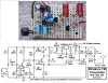
Hi, I am planning to build a FM transmitter for my school project. There are a lot of designs available on the internet and I simply don't know which to choose. I decided to choose a simple one from the cryptomuseum webpage. Its circuit is shown below.
jk_circuit.png

I am new to RF design. Please forgive my ignorance. I would like to ask a couple of questions.
1) Why the antenna is wired to the inductor in the manner shown above? Won't the frequency of the signal be affected?
2) Why a potentiometer is connected to the mic instead of a fixed one? Is it because of the issue of impedance matching?
3) Could this circuit be improved somehow? Is there an alternative circuit instead of the one shown above?
4) I tried to analyze the feedback loop of the oscillator circuit (the LC tank with the second transistor) by hand but my equations got complicated quickly. The question is: Is the resonant frequency of the oscillator set solely by the LC tank or will it be affected by the 3pF capacitor in the positive feedback loop?

Thanks in advance for your patience and guidance.
 
Welcome to ETO, daveclifford95!

As to your questions:
1. Yes, it will. And it's a so-called "tap" on the coil (or a signal "pick-up") for propagation. Also its length will be a factor in a frequency shift. But the trimmer's range (2-22uF cap) should allow for adjusting the oscillator frequency into the FM band. What will have the most significant effect on oscillator frequency will be the coil's (inductor's) actual, physical construction (number of turns, diameter and length), as noted in the circuit description.

2. The pot is an audio input volume control.

3. I'm sure it could but for your first effort, I'd avoid "improvements" until you get this one working correctly.

4. Without knowing, for sure, what the inductance of the coil actually is (or the trimmer's value at the preferred resonance, for that matter), you'll be hard pressed to determine the tank's resonant frequency mathematically. If it were me, I wouldn't bother at this point. Once you've successfully created a working circuit, with a resonant frequency within the 88-108MHz range, use that frequency (however you determine it (I'd guess from an FM radio dial/readout) in the formula for resonance to determine the inductance (while guessing at the value of the trimmer) for the inductance of the coil. It'll be off a bit due to the effect of the antenna. And the 3pF cap will influence the resonant frequency but, again, it should not exceed the influence of the trimmer.

Now, with all that said, note carefully the parts layout for the circuit displayed at the cryptomuseum page. Within the oscillator portion of the circuit, relative component position will have an enormous effect on its operation, especially concerning the arrangement of the trimmer, coil (plus tap) and cap. It'll take a lot of "tweaking" of those positions to get to all work together properly. And make sure your fingers are nowhere near the circuit when you test for the resonant frequency (the noted "hand effect" in the circuit description).

Good luck and have fun.
 
Welcome to ETO.

1) Why the antenna is wired to the inductor in the manner shown above? Won't the frequency of the signal be affected?
Yes the signal frequency will be affected by the capacitance of any object which comes near to the antenna.
As for why is it tapped like that, it is to reduce the loading which the antenna will impose on the tuned circuit.

2) Why a potentiometer is connected to the mic instead of a fixed one? Is it because of the issue of impedance matching?
The variable resistor (potentiometer) is there to allow the frequency deviation to be adjusted. ie how loud the signal from the transmitter sounds in a receiver.

3) Could this circuit be improved somehow? Is there an alternative circuit instead of the one shown above?
Yes it could be improved, it is an awful little circuit, but it will work within its limitations.
So for a learning exercise for school, capitalise on the circuits shortcomings and explain why a much more complex circuit is required to build a transmitter which can be used in the real world.

4) I tried to analyze the feedback loop of the oscillator circuit (the LC tank with the second transistor) by hand but my equations got complicated quickly. The question is: Is the resonant frequency of the oscillator set solely by the LC tank or will it be affected by the 3pF capacitor in the positive feedback loop?
Analysis of this circuit is difficult because there are parasitic elements which do not show up on the schematic.
For example:
All the wires have inductance.
All components have stray capacitance , to ground and to each other.
The transistor junctions have capacitance which varies with voltage. That is how the FM modulation works by the voltage from the microphone varying the base-collector and base-emitter capacitances.

I notice that as I have been typing cowboybob has answered in a similar manner.

JimB
 
Thanks to both cowboybob and JimB detailed explanations. I forgot to ask one question: looking elsewhere on net, the second transistor (2N2219) is in the common-base configuration. But I cannot understand why it is the CB configuration. Is it because of the 470pF capacitors that "directs" the signal away from the transistor's base? And why does not the signal enter the transistor through the collector?
 
But I cannot understand why it is the CB configuration. Is it because of the 470pF capacitors that "directs" the signal away from the transistor's base?
Yes, the two 470pF capacitors represent al low impedance at the RF signal frequency and decouple the RF from the base of the transistor.

One thing which is obviously missing from that schematic is a supply decoupling capacitor, there should be at least a 1000pF capacitor from the +ve supply rail to 0v. It would be even better if there were a 0.1uF capacitor and a 100pF capacitor in parallel from the +ve supply rail to 0v.

The transistor is in common base configuration, the input is the emitter and the output is the collector.
The CB configuration has a low current gain, but because the input impedance is low and the output impedance is high, there is a large voltage gain.

JimB
 
It probably will not work if you build it on a solderless breadboard because the stray capacitance between the rows of contacts and the wires all over the place will be too high. Build it compactly soldered on stripboard with each strip cut short or in a pcb.
Its radio frequency will change as the battery voltage runs down because it is missing a voltage regulator.
It will sound muffled because it is missing pre-emphasis (look it up).

My FM transmitter design addresses and corrects all the problems and sounds great:
 

Attachments

  • FM tx mod4 pic and schematic.jpg
    FM tx mod4 pic and schematic.jpg
    196 KB · Views: 447
audioguru May I ask what are the purposes of second stage and third stage BJT? There are LC tanks in both stage, do both of them act as oscillators?
The first transistor is a microphone preamp with pre-emphasis.
The second transistor is the radio frequency oscillator.
The third transistor is an RF amplifier to isolate the oscillator from the antenna so that something moving towards or away from the antenna does not change the radio frequency due to the change in capacitance.
 
Status
Not open for further replies.

Latest threads

New Articles From Microcontroller Tips

Back
Top