Electro Tech is an online community (with over 170,000 members) who enjoy talking about and building electronic circuits, projects and gadgets. To participate you need to register. Registration is free. Click here to register now.
Welcome to our site! Electro Tech is an online community (with over 170,000 members) who enjoy talking about and building electronic circuits, projects and gadgets. To participate you need to register. Registration is free. Click here to register now.
Altima: The cameras are cheap (often free), so parts cost is not much of a concern. I would do it using two cameras modified as in the link above. Then, use a standard astable multivibrator circuit to switch the power supply between them. This way you work with lower voltages and easily available schematics/parts.
As Sceadwian mentioned, its illegal to impersonate an officer. However, flashing lights have uses outside the law enforcement community. Please use these ideas in a responsible way.
You can always just increase the voltage, and pray the circuit hold together, and it will for a short period of time. You can also just copy the camera flash circuit and increaes the size of the transformer and transistors. The transformer is the weak link I believe.
You certainly cannot increase the voltage. It is designed for 1.5 and takes up to 700mA. You cannot change anything. I have already put hundreds of old "guts" into strobes and made them blink automatically.
Here is the circuit: **broken link removed**
You certainly can if the voltage is well controlled for short burst durations of pulses. I have done so successfully, this is for short term use of course. As discussed already if what the OP wants is a long term solution to driving flash bulbs especially for a needed safety vehicle application, using a camera flash circuit is NOT the answer.
Sceadwian You certainly know what you are doing. I am only an idiot that produced over 100 with auto flash and tried to use 3v and overheated the transistor. The transformer was saturated. But you know better. I am only a fool.
I built a heavily overpowered flash in 1984 from camera flash components. It never worked? It sure looked to me like it worked. It still looks like it works....
A camera flash cannot operate as a strobe with the same capacitor and voltage for long. The glass tube itself will overheat and crack from the flash pulses.
You MIGHT think you'd just use a smaller flash capacitor, thus limiting the energy of each flash. This will work, bu the strobe's efficiency (and color temp) degrades quite a bit if you reduce the flash power, making it a somewhat poor design. A lot of cheap strobes DO work like this, and appear to use flashtubes similar to cameras. They may BE surplus camera tubes, I don't know. Perhaps this is what happens to all those "disposable cameras" after they're shipped off to be developed.
I built my flasher for a theatrical effect and hoped it would work for maybe a week or two. Imagine my surprise 25 years later...
The tubes (3 of them) are 25mm long and about 2mm in diameter. I charge 150uF to about 350V, and fire each tube about once per second (the assembly flashes 3 per second). They get hot in a hurry but I don't leave them on for very long.
Sceadwian You certainly know what you are doing. I am only an idiot that produced over 100 with auto flash and tried to use 3v and overheated the transistor. The transformer was saturated. But you know better.
Of course it's possible to power a strobe to work from other voltages, I've seem many strobes working from 12V.
In the case of a disposable camera, you just need to rewind the primary for higher voltages or simpler still, reduce the duty cycle of the primary waveform.
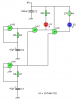
Here's a circuit I came up with using a quad Schmitt trigger NAND gate.
U1A is a high frequency oscillator and U1B is a low frequency oscillator. I've not calculated the frequencies so you might need to change the resistor and capacitor values to slow/speed it up, depending on your preference.
I have another idea which will work with four CMOS inverters, so will work with a quad NAND, NOR or a hex inverter IC, if you're interested.
suppose you could have 10 chargers, and 10 capacitors, and ''open'' each capacitor to the same bulb with a decade counter, hopefully by the time the 10th capacitor is discharged, the first one is charged again
No colin you're not a fool, but I have done this before, and I never said doubling the voltage was safe, increased voltage WILL increase the flash rate of the stock circuits normal ability, I never quantified it, and as I explicitly stated will shorten the life of the circuit if it's done for anything but brief periods of time.
suppose you could have 10 chargers, and 10 capacitors, and ''open'' each capacitor to the same bulb with a decade counter, hopefully by the time the 10th capacitor is discharged, the first one is charged again
1) The one tube will get hot. Give it time to cool while you're charging. Use one tube per capacitor.
2) A typical decade counter does not have the capability to carry the flash current.
3) You can design a circuit that "hopefully" will work. Or you can do the math.
This site uses cookies to help personalise content, tailor your experience and to keep you logged in if you register.
By continuing to use this site, you are consenting to our use of cookies.

")