Continue to Site

Welcome to our site!

Electro Tech is an online community (with over 170,000 members) who enjoy talking about and building electronic circuits, projects and gadgets. To participate you need to register. Registration is free. Click here to register now.

  • Welcome to our site! Electro Tech is an online community (with over 170,000 members) who enjoy talking about and building electronic circuits, projects and gadgets. To participate you need to register. Registration is free. Click here to register now.

Bug zapper diagnosis

Status
Not open for further replies.

Leadfree

New Member
I have one of those bug zapper tennis raquet's which no longer works.
You used to plug it into 240volts and it would charge up ready for use, then you flick a switch, and press a button when swatting at fly's.
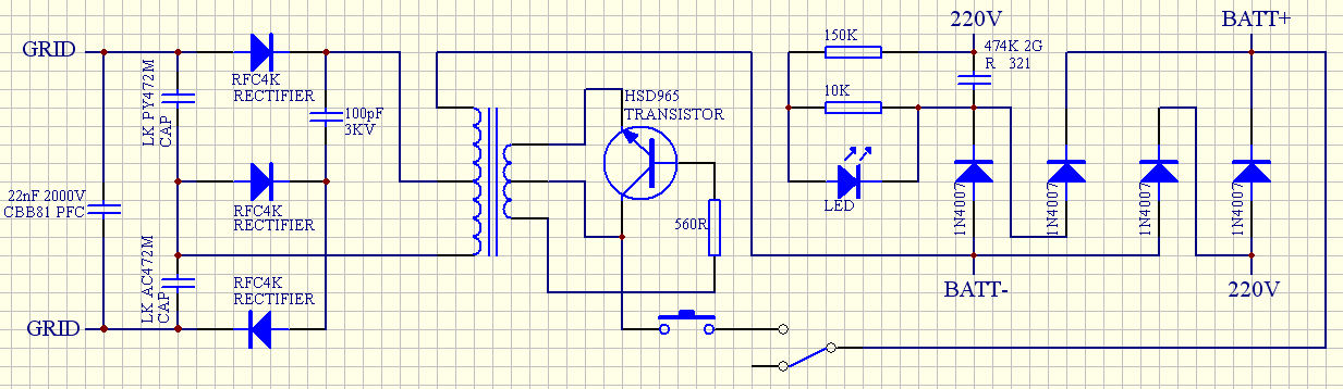
As i mentioned, it no longer works. Im wondering, the grey rectangular object in the picture, could that possibly be a storage capacitor? When you have it plugged into 240v to charge, it seems to be getting 240v at the (+) and (-) terminals on it.
The large brown cap at the end of the circuit board is rated at 2000v, so i assume thats what this little beast is meant to output, but i havent got anything that can read that high, so i cant just plug a variable power supply onto the terminals.

**broken link removed**
 
Last edited:
Tracing the circuit, looks like its the only thing it could be. Looks like this circuit is useless for running on 3v then.
Buggered if i understand how the transformer works, its got six pins, three on either side.
 
OK, no one spoke up yet and so I'm guessing no one has a clue. My guess on the grey block is a capacitor (same as yours) and probably buggered. As for fixing it, resolder everything and if it still don't work throw it in the trash.

The good thing is that my post may wind up the analogue guys and they may shoot me down.

Mike.
 
I wouldnt mind getting it working, but noone on this forum seems to know anything about em. Its been asked a few times before with few if any helpful answers.
 
Any other components we don't see? How about a flat-on photo of the top and the bottom. I'm going to take a guess here. The components on the left of the green capacitor form an DC-DC inverter to produce the the high voltage for the screen. The big black thing, from it physical construction, is a small SLA battery. The large green capacitor and other components form a "transformerless" low-voltage DC power supply to charge the battery. The battery acts like the zener would in these supplies. With an "open" battery the output would climb to line voltage levels. :eek:

But, this is just speculation.

Ken
 
OK to give you guys a hand in helping me, i reproduced the circuit.

I dont have a clue if I have wired the transformer right, all i know is there are three pins on both sides of it. Would that mean both coils are centre tapped?
I just wired it as it looks.

The 474k capacitor on the diode side of the circuit i assume is 470nF with 10% tolerance? Is that right? Its the large green one near the switch on the previous photo.

I dont see how it can use SLA battery, as it gets 240v, it can really only be an electrolytic cant it?

Im annoyed with myself, for such a simple circuit im pretty lost.

**broken link removed**
 
Last edited:
Just as coincidence I just put today a Mozzyzapper video on YouTube.
I had a similar bug zapper lamp which failed of course.
Scrapped everything, exept the casing and the HV bug catcher wire grid.
Built an external PSU from 2 TX 240 / 12 and 12 / 240 Volts for safety.
A simple voltage tripler and get about 1200 V dc.
Works perfect for the last 5 years.
Used coloured LED's as bait.
 
RODALCO nice work, its stupid people throwing things out when with a little ingenuity they can be repaired without wastage.

Colin55, ive just triple checked it and its the same as the circuit i copied it from, can you pls tell me where i might have got it wrong? As i said before i might have got the transformer wrong, as i have no idea how its wired internally. Im pretty sure the transistor is correct, being an NPN, with pinout 1. Emitter 2. Collector 3. Base.
 
Get a multimeter set to low ohms or a 6v battery and 330R and LED and measure the transformer.

You have no continuity on the secondary side of the circuit.
You can see how the primary side is capacitor-coupled to the mains, making the primary about 12v - 20v, but the secondary has no continuity.
 
Last edited:
OK i drew a basic picture of the transformer. It has six pins, but for some reason only four are numbered on the actual transformer.
Four pins are connected together separate from the remaining two, which are also connected together.

**broken link removed**
 
Last edited:
As he said originally, he guessed the internals of the transformer. The schematic will now be correct if you move the top of the primary to the top of the secondary.

Mike.
 
Hmm i cannot edit my original posts. Anyway here are the pics again, i have been having server troubles, all good now.

Original schematic i created
13-zapper.jpg


What is connected in transformer when tested with multimeter
14-zapper2.jpg


Suggested changes to schematic, is this better?
15-zapperv2.jpg
 
Status
Not open for further replies.

Latest threads

New Articles From Microcontroller Tips

Back
Top