Hi all,
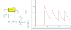
I recently implemented a hysteresis controlled current regulator (INA180 + comparator) for a 2A regulator (1.9A peak in reality). It worked reasonably well at decent current but lower in the range would overshoot, what should have been 20mA ended up at 80mA. I really need good control at the lower end, 20mA ideally. I've now investigated controlling a buck using the same INA180. Here's a picture.

So here's the thing. The FB is 0.6v. With a 75m sense and 2A, 2R*20 = 3v. If the DAC is 0V the resistors values are as shown.
For turn-off, with INA180 at 0V that requires the DAC at 0.75v.
Roughly a 10mA step requires just 1mV of DAC voltage change. In reality I'm unlikely to attain that resolution.
The DAC (which is a PWM into RC) is 3V and ideally if I can increase it to this I'll get better control, but the only way is to reduce the gain of the INA180 and no such current monitor exists. The obvious solution is to reduce the sense resistor but at 50m it begins to loose resolution at such low current through the sense.
If the DAC is 3v, 0.6v at FB, that gives R2 at 6.25k. This will give a INA180 at 0.75v or a 18.75m sense resistor.
Recommendations on which is the lesser evil would be much appreciated. I think what I ideally need is an INA180 equivalent with a gain of 5?
Cheers, Andrew
I recently implemented a hysteresis controlled current regulator (INA180 + comparator) for a 2A regulator (1.9A peak in reality). It worked reasonably well at decent current but lower in the range would overshoot, what should have been 20mA ended up at 80mA. I really need good control at the lower end, 20mA ideally. I've now investigated controlling a buck using the same INA180. Here's a picture.
So here's the thing. The FB is 0.6v. With a 75m sense and 2A, 2R*20 = 3v. If the DAC is 0V the resistors values are as shown.
For turn-off, with INA180 at 0V that requires the DAC at 0.75v.
Roughly a 10mA step requires just 1mV of DAC voltage change. In reality I'm unlikely to attain that resolution.
The DAC (which is a PWM into RC) is 3V and ideally if I can increase it to this I'll get better control, but the only way is to reduce the gain of the INA180 and no such current monitor exists. The obvious solution is to reduce the sense resistor but at 50m it begins to loose resolution at such low current through the sense.
If the DAC is 3v, 0.6v at FB, that gives R2 at 6.25k. This will give a INA180 at 0.75v or a 18.75m sense resistor.
Recommendations on which is the lesser evil would be much appreciated. I think what I ideally need is an INA180 equivalent with a gain of 5?
Cheers, Andrew