Continue to Site
Follow along with the video below to see how to install our site as a web app on your home screen.
Note: This feature may not be available in some browsers.
What voltage are you trying to find?
Also, the cap would not be 10pf as that is way too small, especially with a 1kHz switching frequency.
We already said what that voltage was didnt we? It's the same as the power supply voltage.
Hi
I'm afraid that no one said anything about that voltage, or I might be missing it.
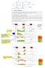
Let's step through Figure 2 and Figure 3 here again.
In Figure 2, the switch has just been closed. Before the switch was just closed, both inductor and capacitor were supplying enough current that voltage drop across 20 ohm load was 9.8V and this goes without saying that note before the switch was closed the capacitor was being discharged and inductor's current was decreasing. But the capacitor starts getting charged and inductor's current also starts increasing from its previously descending value as the switch is closed. Basically two things are happening. First, the voltage on the left of inductor starts decreasing from applied voltage value which in our case is 20V and meanwhile magnetic field of inductor also starts expanding. Second, the capacitor is getting charged up and at the same time voltage is being dropped across the load and this means that current is being supplied to both capacitor and load. These "two things" will continue until voltage drop across the load (or, capacitor's voltage) has reached the value of 10.2V and at that instant switched is opened again.
And you can make it 50uF if 50pF is too small. Thank you.
Regards
PG
When the switch is conducting, you get the source voltage on the left of the inductor, load voltage on the right of the inductor. The inductor is capable of keeping this voltage difference only if the current through the inductor increases. If the rate of current increase slows down, the ability of the inductor to develop voltage diminishes and the voltage accross the inductor will start dropping. As a result of this voltage decrease accross the inductor, either voltage on the left has to decrease or voltage on the right has to increase (or a combination of both).
If you have industrial power supply on the left and resistor on the right, then power supply will wins. Voltage on the left keeps steady, voltage on the right increases.
If you have a solar panel on the left and battery on the right, then battery wins. Voltage on the battery changes little, but panel voltage drops.
If you have an industrial power supply on the left and battery on the right, they'll fight hard and you better be at a safe distance when inductor saturates.
I would suggest di = 1/L*V*dt It is easier to interpret. Voltage put accross the inductor causes increasing current. As soon as there's a voltage, the current goes up.
In case of solar panel, the voltage is maintained by the input capacitor, not by the panel.
Q4: The only thing connected is the load, wich draws relatively constant current from the capacitor, so it's relatively flat.
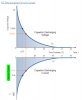
The article is correct. Discontinuous mode occurs for light loads when the average current in the inductor (in steady state) is less than the peak value of ripple current.
I dont think that is the right way to think of it.Let's see if I'm picturing it correctly. Note that light load equates to high resistance which does take a lot of power. In a buck converter if the load resistance is too high then not enough current will be able to pass thru the inductor which will result in less magnetic field around the inductor and hence it results in less ability of the inductor to sustain current when the switch is off. In other words, if it takes 1s to rise the current from 0A to 0.5A, the rise rate of current will be less than the case when the current only takes 0.5s to rise from 0A to 0.5A.
It only happens briefly with heavy loads: either at startup or during transients. Steady state discontinuous mode only happens with light loading.Does this mean that discontinuous mode cannot happen for a heavy load (i.e. low resistance)?