Continue to Site

Welcome to our site!

Electro Tech is an online community (with over 170,000 members) who enjoy talking about and building electronic circuits, projects and gadgets. To participate you need to register. Registration is free. Click here to register now.

  • Welcome to our site! Electro Tech is an online community (with over 170,000 members) who enjoy talking about and building electronic circuits, projects and gadgets. To participate you need to register. Registration is free. Click here to register now.

Buck/Booster converter problem?

Status
Not open for further replies.

cabrall

New Member
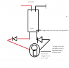
Hey Long story short I am building a simple power supply. When I add diodes on the output of the buck boost converter I lose regulation on the output UNLESS I have a small load attached. I dont really lose regualtion but voltages start at different levels. Example supposed to be 12-65v, after diodes its 48-99v. but its not a real voltage its like floating. ( BUT if i measure before the diodes on the converter itself regulation and voltages is fine)

So with diodes on the output the Buck Boost converter has improper regulation unless there is a small load. With a load all Regulation is restored normally with correct voltages. I have tried many converters and many types of diodes including schottky diodes. Why is this happening? are my diodes not switching fast enough? I just want diodes on the output for spikes/reverse charge. I just don't get how adding diodes on the output is effecting the regulation. The only thing i can think of is I am messing with the DUTY cycle feed back or something? I was thinking of just adding the meter on the converters output before the didoes to see the proper regulation without a load? please help lol
 
Last edited:
This converter:
https://www.ebay.ca/itm/DC-DC-Converter-15A-400W-Boost-Converter-Step-up-Voltage-Buck-Boost/132841718224?_trkparms=aid=111001&algo=REC.SEED&ao=1&asc=20160908105057&meid=2ad0efeb057d4788827bb1336af73faa&pid=100675&rk=4&rkt=15&sd=321576507977&itm=132841718224&_trksid=p2481888.c100675.m4236&_trkparms=pageci:05be912a-53e2-11e9-bd54-74dbd1802f30|parentrq:d4fd995b1690a9cb57031844ffece18a|iid:1

The input is straight 12v. The output one diode one way and another the other way. The Diode choice was a 10 amp 1000v diode. I tried other ones too.

About the small load? sorry for my newbie question but What Load can I put that would variate with the voltage and would not overheat? I have no problem putting a load, I can't think of anything that would work with the voltage ranges. ( that is easy to install and doesn't take up space). I intially thought a power resistor but wouldnt I be getting tones of heat on higher voltages or vise versa on the lower end depending on what resistor i use?
 
Its a poor diagram but maybe it will help what I am trying to say.
 

Attachments

  • help.png
    help.png
    80.1 KB · Views: 144
Are the didoes supposed to effect the output variation? are they not the right ones? is that even a thing lol
 
I think your getting a measurement anomaly.
The diodes might be allowing peaks through which your meter is reading.
Why do you have diodes on the o/p?
Its not uncommon for an smps to have a minium load, some control ic's have a minimum pulse width so you need to load the supply enough to shunt this much energy.
 
The link above describes it as a "boost constant current module". Is it constant current or voltage?

Mike.
 
Dr pepper you nailed it. I used a different meter and all works fine. In the end it was my meter only picking up the peaks. Thank you !
To answer your question I am using diodes on the output to make sure I dont get any spikes/unwanted voltages when charging or using a motor. Is this not the right thing to do? I am genuinely asking.

Next question is ok to use a FSU10A60 as a blocking diode on the output. Or should I use the 10 amp 1000v Diodes. I dont have much options in the moment lol. I figured the FSU10A60 would work well because there fast switching/High Surge Capability .

Lets say I wanted to use a load that can go from 12v to 65 without getting too hot what would I even use lol?

P.S Why would my meter do that>? Its a Agilent 34401a? I dont get how a 15 dollar meter works but the expensive on throws out a false reading? weird
 
Last edited:
You dont need the diodes.
But if you want you can put a diode across the motor in reverse bias, ie the cathode (silver stripe) goes to the + end, this will clamp any noise to 0.6v.
Your expensive meter is telling the truth, where as the cheaper one is ignoring the peaks, this is to be expected.
I use a cheapo meter and rubbish 'scope all the time, the good stuff only comes out when its needed.
 
Status
Not open for further replies.

Latest threads

New Articles From Microcontroller Tips

Back
Top