Continue to Site

Welcome to our site!

Electro Tech is an online community (with over 170,000 members) who enjoy talking about and building electronic circuits, projects and gadgets. To participate you need to register. Registration is free. Click here to register now.

  • Welcome to our site! Electro Tech is an online community (with over 170,000 members) who enjoy talking about and building electronic circuits, projects and gadgets. To participate you need to register. Registration is free. Click here to register now.

Brushless motor driver keeps popping driver chips.

Status
Not open for further replies.

Triode

Well-Known Member
I know I posted a few weeks ago about a motor driver, but this is a different problem with the next version. Now the switching time (problem on the last one) is great. But when the motor is starting up sometimes it destroys the driver chip. A little pinhole pops out right next to the VCC pin and it dies. I would guess this points to a voltage spike on VCC but I'm not certain.

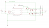
This is a single half bridge, to make a brush less driver I used three of them. It was powered from 15 volts on a power supply with a 10 A current limit. The drive code has been used on several smaller motor drivers and works well, I can provide details if needed, but it simply uses the hall sensors to run switching off of a commutation table. In most cases I was running it with 30 kHz PWM, but the behavior was similar with 20 kHz. I measured the rise time on the high side FETs at 480 ns and the fall time at 390 ns, for the low side it was 420 ns rise, 430 ns fall.

Usually it runs the motor very well. The transistors don't warm up at all when driving 15V at 7A. But sometimes, usually after 5-10 runs, at startup the motor warbles and one of the driver chips pop. If not protected the micro-controller is destroyed too. After a failed test I ran the outputs from the MCU through 1N4148 diodes with a pull down resistor on the gate driver side and that seems to at least keep it from killing my MCU.

In case it's hard to see:
diodes: 1N4148
transitors: CSD18536 - 60 V, 1.3 mΩ "NEXFET" Mosfet, package continuous drain current limit 200A, Power dissipation 375W, Gate charge 108 nC (10V)
driver chip: NCP5183
https://www.onsemi.com/pub/Collateral/NCP5183-D.PDF
4.2A high/low side driver

upload_2018-1-17_23-7-13.png

note, in assembly I run a jumper wire to Vcc, if I need to add some protection that could give me a convenient way to redo it without remaking the entire board.
upload_2018-1-17_22-54-34.png


driver chip diagram

upload_2018-1-17_23-9-2.png


Thank you very much if you read all that!

So my first inclination is to suspect that I need to separate VCC and put some protection on it. After all this schematic does not show Vhv and Vcc being on the same line. This is supposed to be a battery powered application so they will actually be off of the same source. But I would assume some sort of protection is a good idea.

Would the best approach here (if Vcc protection is the problem) be a zener diode at say, 18V, with a resistor into Vcc? Or would some sort of regulator make more sense?

I also realize that might not be the only issue and I could be looking at the wrong problem. It seems likely to me that an inductive kickback is destroying my chips.

Thanks again!
 

Attachments

  • upload_2018-1-17_22-56-12.png
    upload_2018-1-17_22-56-12.png
    98.6 KB · Views: 104
Just quickly...
It's probably not related to your problem, but it's good practice to put a separate gate stopper resistor on each transistor. This not only dampens ringing, but also prevents the FET with the lowest threshold from taking all the switching load as it clamps the gate drive at it's miller plateau.

Did you say that FETs are surviving - just the driver getting popped?
 
When you say "warbles" do you mean it oscillates as if it can't decide which way to go? Does it try to start in the wrong direction?

I use commercially made controllers for my model brushless DC motors. One sees that type of behavior quite often with a load (propeller) attached, so I asked the manufacturer. I was told that at dead stop, indeed the motor can't tell which way to turn, so it hunts for the correct direction. Translated to your case, that hunting might lead to excessive current. I did not go further to find out how the commercial controllers work, but one thing to consider would be some sort of current limiter during start. A soft start might be one approach.

As a test, if you start the motor turning by hand in the correct direction, do you avoid the problem? Do you have some sort of load on the motor?
 
Provide a scope of the traces between gate-source on startup (when it blows and doesnt blow if possible) and the Vcc current into the drain.

What is your startup algorithm?

When you say "warbles" do you mean it oscillates as if it can't decide which way to go? Does it try to start in the wrong direction?

I use commercially made controllers for my model brushless DC motors. One sees that type of behavior quite often with a load (propeller) attached, so I asked the manufacturer. I was told that at dead stop, indeed the motor can't tell which way to turn, so it hunts for the correct direction. Translated to your case, that hunting might lead to excessive current. I did not go further to find out how the commercial controllers work, but one thing to consider would be some sort of current limiter during start. A soft start might be one approach.

As a test, if you start the motor turning by hand in the correct direction, do you avoid the problem? Do you have some sort of load on the motor?
he says his motor is not sensorless so this should not be the case.
 
Last edited:
The transistors don't warm up at all when driving 15V at 7A.
With that sort of current I'd be inclined to slap beefier diodes than 1N4148 across the fets. Schottkys?
Adding some resistance between Vcc and pin 5 of the driver IC would help to reduce transients on the IC supply.
 
I think I agree with both of those recomendations.

If the FETs are staying intact then there's not much that could kill your driver IC other than an overvoltage on Vcc. As Alec suggests, an RC filter - and possibly even a Zener clamp - to isolate the driver supply from the high-current supply would seem sensible. You might even like to feed them through a regulator.

If your power supply is a laboratory-type PSU (you say it's current limited) with very little output capacitance then there's nowhere for the motor's back-emf to go when it deccelerates and rail voltages could quickly end up far higher than normal. You might find that, powered from a battery, the problem goes away.
 
I would remove those little 1N4148 diodes immediately. They are likely frying and causing a short circuit.
The body diodes on your MOSFETs are all you need, they are more than capable of handling the reverse current.

64A0A58D-5574-42C6-B215-21A484F47B63.jpeg


The diodes are a good idea when you use BJT or Mosfets without such robust body diodes. Your mosfets can handle 100A!


FD74F29B-0102-48BD-A08A-93D8CD8B1B91.jpeg
 
Also, read the top of page 11 of the datasheet. There are careful layout and application rules to "prevent the device from destroying itself". Parasitic inductances are a big deal in this device and driving inductive loads (like your bldc motors).

https://www.onsemi.com/pub/Collateral/NCP5183-D.PDF
 
Thank you for all the help. For now I've changed my circuit to take the VCC and the bootstrap resistor input off of the motor supply line. They still use the same supply but it goes through a buck converter, and an 18 volt zener first. For a while it seemed to be working, but it still kills a chip now and then.

It seems to only happen when I go above 80% duty cycle on the PWM. I wonder if I'm depleting the bootstrap capacitors. I'm testing with a scope now to see if they're draining out. Unfortunately it's hard to test without going through a lot of driver chips in the process.

If it is the diodes they don't seem to be damaged after a chip gets destroyed. I can replace the chip and it lasts several cycles. I may be misunderstanding but it seems like if the diode was failed it would kill the new chip right away.

Sorry I didn't reply when you're all helping me out, I thought I'd posted a follow up and I don't see it.

When I said warbles I suppose that wasn't a very technical term. I mean if I'm turning up the current limit it tends to burn up if I stay in the region where it's just barely starting to move for too long. But now that I separated the power supply for VCC and the bootstrap this isn't the case. It seems to die almost at random at the start of a pulse. I was testing it by having it kick up to full speed on the command with the power supply already turned up. It survives that just fine as long as the duty cycle is 80% or less. At 90 or so it will handle it with no mosfet heating until at some point 10 or 20 pulses in, the driver chip smokes.

Thanks for all the help! I'll get some traces on the capacitors and gates and post them soon.
 
With further testing I'm pretty sure the bootstrap caps are running out of power. I monitored them with a differential probe and during startup when it spends more time on the same phase they started to drain.

I'm thinking of using this circuit to eliminate the issue, mostly because I have all the needed parts on hand.

**broken link removed**

**broken link removed**

Unfortunately, as a mechanical engineer, not an electrical one, I can't say I 100% understand how this circuit works. So I'd be blindly following the schematic and if it doesn't work I probably won't know why.

The datasheet also shows this expected output, which I can scope for so I'll know if that's not occurring, but hopefully it will work or I can gain enough understanding of it to debug it if it doesn't.

**broken link removed**
The ON Semi datasheet had specs on the charge pump running out of steam. I think this is worthy of some effort.
 
With further testing I'm pretty sure the bootstrap caps are running out of power. I monitored them with a differential probe and during startup when it spends more time on the same phase they started to drain.

I'm thinking of using this circuit to eliminate the issue, mostly because I have all the needed parts on hand.

**broken link removed**

**broken link removed**

Unfortunately, as a mechanical engineer, not an electrical one, I can't say I 100% understand how this circuit works. So I'd be blindly following the schematic and if it doesn't work I probably won't know why.

The datasheet also shows this expected output, which I can scope for so I'll know if that's not occurring, but hopefully it will work or I can gain enough understanding of it to debug it if it doesn't.

**broken link removed**
It's a fancy charge pump.

I forget the details and am too sleepy to think about it too hard. But if memory serves me right, the zener provides a +15V regulated that is only activated when the high-side gate is on. The current path for this regulator when high-side gate is on is:
1. through Rs. Rs is a current sense resistor and therefore has near negligible resistance and near negligible voltage drop by design.
2. past the VS pin through the zener diode which drops 15V across it to produce the regulated voltage
3. and through the 100K resistor which drops all the voltage other than the 15V from the zener.

Since the 15V zener sits on this resistor, the whole regulator is not referenced to ground. Rather, the 15V hangs just underneath the positive rail. It's a -15V regulator referenced to the positive rail.

It powers the 555 timer which constantly switches the OUT pin between that hanging +15V and ground. Since this OUT pin is connected to the negative terminal of the charge pump cap, it alternately:
1. charges up the diode to 15V through one diode (just like the normal bootstrap cap)
2. forces the cap to sit on top of that 15V which causes the charge pump cap to discharge into the actual boostrap cap to replenish it without the low-side needing to go turn on. One of the diodes stops charge from the bootstrap going back into the charge pump cap while the other cap stops the charge pump cap from discharging when its boosted up.
 
Last edited:
Thank you for the explanation, that makes sense to me, or at least a lot more than I could figure out from looking at it on my own.

This is going to have a lot of ideas cause at this point I'm just trying to make this chip stop popping at all costs.

Is there a reason the the caps running low would destroy my driver chip? I've just tested a design updated from the one I posted with VCC on the driver chip, and the supply to the bootstrap resistor coming from a second power supply. There should be no way a surge can get to the chip that way. They do share a common ground. It seemed to work, at least it made it so I could run the driver off of a 14.8V battery in short pulses at 80% duty cycle and it seemed to work well. The transistors stay cool and nothing broke.

Like this
upload_2018-1-24_21-31-57.png

Then I increased the voltage to two batteries. It should be able to handle 30V. The fets are rated for 60V. But now after 2 pulses (50 ms long) one of the driver chips burnt out.

I'm willing to go way overkill on this to make this thing work, so any protection I can add without keeping it from working is worth while. All I can see that's left for the chip to be destroyed by are:

  • The connections into the FET gates - Is there any possible way that the fet gates would create a damaging surge? If so it's not destroying the FETs. Could they be destroying the chip by making it exceed it's 4A drive rating? Maybe I just need gate resistors of say 5 or 10 ohms?
  • HB is still connected to the main circuit but it's rated to 618V so I doubt that's the problem
  • Ground is an interesting one. Could that be the problem?
There is this note on protecting the chip that I don't quite understand:

"Do not let high current flow through trace between GND_pin and CVCC even a small parasitic inductance here will create high voltage drop if high current flows through this path. This voltage is added or subtracted from HIN and LIN signal, which results in incorrect thresholds or device damaging"

This drawing is what they're referring to
upload_2018-1-24_21-43-36.png

GND is the 3rd pin from the left on the bottom, sharing a ground with the low side transistors source pin. That little island under the C in C_VCC is connected to VCC, fourth pin from the left on the top. I don't understand why current would flow there.

I would want to just tie ground for the chip right into the microcontroller and have it share a ground with the separate supply to the VCC on the chip, but I'm pretty sure to switch the low side the grounds need a common connection. Maybe I'm on the wrong track here. If ground was getting offset and causing HIN and LIN to switch at the same time that would damage the fets, not necessarily the fet driver.

I also found this note on driver protection:
upload_2018-1-24_21-54-31.png
It seems like at any rate, this couldn't hurt. I have fly-backs from the power output but not on the gate. I'm not sure what specifications to look for on the schottky diodes, other than that they should be "low voltage drop".

I'm thinking maybe these
https://www.digikey.com/product-detail/en/stmicroelectronics/STPS5L40/497-12672-1-ND/2864638

DC reverse voltage: 40V
Current Average rectified: 5A
Speed: fast recovery >500 ns
Voltage forward: 500 mV

I figure that qualifies as low forward voltage, and I knew they needed to be fast. I'm not sure what current rating I need, so I'm just guessing on 5A being enough.

I'm not totally sure this note applies to my driver, as the app note mentions BJTs and my driver contains fets, which generally can handle reverse conduction, but perhaps not enough.
upload_2018-1-24_22-33-16.png

Thanks for all the help. I know this is quite a dump of ideas. But I'm a mechanical engineer and this is a crash course for me. For now I just want my driver to stop exploding, even if it's overkill on the protection in some places.
 
Last edited:
Is there a reason the the caps running low would destroy my driver chip? I've just tested a design updated from the one I posted with VCC on the driver chip, and the supply to the bootstrap resistor coming from a second power supply. There should be no way a surge can get to the chip that way. They do share a common ground. It seemed to work, at least it made it so I could run the driver off of a 14.8V battery in short pulses at 80% duty cycle and it seemed to work well. The transistors stay cool and nothing broke.

Not that I can think of. Driver chips have an undervoltage lockout to prevent partial drive of the MOSFET to stop the MOSFETs from getting damaged. I don't see any inherent reason why the driver chip itself would be damaged by anything but an overvoltage, overcurrent, or ringing (which would be ultimately result in in one of the former two).
 
When I use MOSFET drivers like this I also put a relatively large (1uF) series capacitor on the driver outputs. This prevents driver lock-up which can lead to both high and low side transistors being on simultaneously. Gate discharge resistors may also be a good idea.
 
When I use MOSFET drivers like this I also put a relatively large (1uF) series capacitor on the driver outputs. This prevents driver lock-up which can lead to both high and low side transistors being on simultaneously. Gate discharge resistors may also be a good idea.

In the OP's case, wouldn't that impede his goal of continuous duty cycle?

I've not heard of this before. Might come in useful someday (like two weeks form now lol). How does it prevent driver lock-up?
 
Last edited:
Doesn't that just artificially increase the gate capacitance by a massive amount? And in the OP's case, wouldn't that impede his goal of continuous duty cycle?
I didn't see the OP mention anything about needing a 100% duty cycle. Did I miss it?

The series capacitor has never caused me any grief due to increased capacitance, and the switching waveforms are still sharp and clean. Now that you mention it, though, I'm surprised I haven't seen at least some difference. Might have something to do with the 1uF being in series with the gate capacitance during the switch-on portion, but when it's being switched off you're right, it would be effectively placed in parallel....

If the OP does indeed need 100% duty cycle then forget this answer, you would NOT want the DC-blocking cap in that case.

Regarding the "warble" at the higher-duty end of things, are you sure that's not just the signal from your micro? A lot of devices struggle to modulate PWM to near 100% duty.

Oh, this is just one thread in an ongoing series of threads for the same project. So yeah, we know he needs 100% duty cycle.

I retracted my comment about the increased gate capacitance because I initially read it as a parallel cap rather than a series cap. A series cap would form a capacitive divider where almost all the voltage would be accumulated in the gate cap since it's so much smaller than the 1uF series cap. Is there an issue switching it off? I don't see why it would be in parallel during switch off.

EDIT: Oh, I see why it's parallel during switch off. I don't think it matters because the gate cap would balance out charge with the series cap resulting in a near zero voltage due to their size difference.
 
Last edited:
Status
Not open for further replies.

Latest threads

New Articles From Microcontroller Tips

Back
Top