Continue to Site

Welcome to our site!

Electro Tech is an online community (with over 170,000 members) who enjoy talking about and building electronic circuits, projects and gadgets. To participate you need to register. Registration is free. Click here to register now.

  • Welcome to our site! Electro Tech is an online community (with over 170,000 members) who enjoy talking about and building electronic circuits, projects and gadgets. To participate you need to register. Registration is free. Click here to register now.

Broken wires Bissell vacuum

Status
Not open for further replies.

Westindieman

New Member
I have opened up to see whats wrong and can see the wires but dont know where they should connect to. I have taken it to a repair shop but they say as I have opened it they wont fix it. Can anyone suggest how these wires should be connected?


Attachments

  • IMG_20201025_171240.jpg
    IMG_20201025_171240.jpg
    3.1 MB · Views: 333
I can't even recognize the parts.

Usually, there is a motor (2 wires)
Power in (2 wires)
Switch (2 wires)

The yellow thing is a capacitor. What is printed on it?
A low value like 0.1 uF could mean across the switch or across the motor.
if the motor then it helps eliminate RFI. If across the switch, it's to surpress arcing across the switch contacts.

Most vacuums use universal motors and have brushes.

One of my vacuums has a "dirt indicator". It glows when it's actually picking up dirt.

The power cord can be white black and green or brown, blue and green yellow stripe. See: https://www.ledlightexpert.com/Brow...is-black-and-hot-and-which-is-white_b_13.html

The switch goes in series with the black or brown wire.
 
Thanks for replying, I have attached an image of whats written on the capacitor. The disconnected wires are black from the capacitor, and a blue wire. I will have a look at your link in the morning, thanks
 

Attachments

  • IMG_20201029_013901.jpg
    IMG_20201029_013901.jpg
    845.2 KB · Views: 354
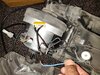
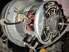
Look at my annotated version of your picture:
Disconnected Wires 2.png


Within the limits of what I can see on the picture...

1 is the incoming neutral wire from the mains.
6 is the incoming live wire from the mains, which goes to the switch (out of picture).
7 is the live wire to the motor from the switch.

3 is one connection to the motor.
5 is the other connection to the motor.

Wires 1, 2 and 3 should be connected together.
This will put the mains live (7) to one side of the motor (5), and mains neutral (1) tot he other side of the motor (3),
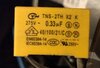
and the yellow capacitor (which is an X2 rated type) will connect in parallel with the motor.

The lump of white plastic (4) on the end of wire (3) is an insulating sleeve, and should be removed before connecting 1,2,3 together.

When the connection 1,2,3 has been made, it must be insulated well.
Similarly point 5 must also be well insulated.

A general comment which I feel I must make,
the wiring appears to be very poorly made, short ends of wire twisted together and not well fastened.

Good luck!

JimB
 
JimB

Nice catch on the crappy wiring. Hanging wires are no good at all which is probably why it failed. The wires might be better extended with solder and heat shrink tubing and tied down before they are terminated. Wires with the crimp caps are common though.

These **broken link removed** might be a better choice for you.

If you can solder, you can cover the soldered splice with heat shrink tubing **broken link removed**

Unfortunately, lengths of wire (wire by the foot) are difficult to come by too. There's all sorts of stuff to manage wires and sometimes buying 1 is difficult.

if your in the US: (wire) https://www.mcmaster.com/wire/wire-and-cable/wire/wire-gauge~18/?SrchEntryWebPart_InpBox=wire You might want 16 AWG.

Wire management: https://www.mcmaster.com/wire-management?SrchEntryWebPart_InpBox=wire

Splices: https://www.mcmaster.com/electrical-wire-splices?SrchEntryWebPart_InpBox=wire
there are crimp tools for insulated and non-insulated splices.

Look here https://www.mcmaster.com/terminals?SrchEntryWebPart_InpBox=wire under ferrules. they keep stranded wire so screws can clamp to them.

These https://www.digikey.com/en/products/detail/molex/0391001902/4988889 are always nice, but need to be used with ferrules usually.

There are other issues like using screws for plastic or rivets.

or I could be just barking up the wrong tree.
 
Wire [7] in Jim's notes has a kink in it, just where he has labelled it.
I suspect it is supposed to fit in the notch just below it in the plastic rib, but has been trapped out of that in the past.

Make sure the wire core has not broken there, and that the insulation is OK?
 
Well wow! I'm overwhelmed with all this help and so quickly, im really impressed! I will look at it over the weekend and in the meantime look at UK sources for bits to make a good fix. Thanks again.
 
Just one more check please. Just inside the motor casing I can see this brown connector, should is this missing something?
 

Attachments

  • IMG_20201029_133458.jpg
    IMG_20201029_133458.jpg
    2.3 MB · Views: 294
Earlier I said:
Within the limits of what I can see on the picture...

I am now thinking "Hold on a minute..."

Where did you get this thing?

This is looking less like a cheap piece of junk where the wiring fell apart,
and more like something which failed,
someone pulled it apart to investigate the fault,
decided that it was beyond economical repair and dumped it.

JimB
 
Earlier I said:


I am now thinking "Hold on a minute..."

Where did you get this thing?

This is looking less like a cheap piece of junk where the wiring fell apart,
and more like something which failed,
someone pulled it apart to investigate the fault,
decided that it was beyond economical repair and dumped it.

JimB

No mate, it was working right up until it wouldnt power on 2 weeks ago. We've had it about 5 years. Its quite possible nothing is supposed to be connected there but I am checking as the silver shielding may have come out of there. It could be ive disturbed somethings while opening the case.
 

Attachments

  • IMG_20201029_145532.jpg
    IMG_20201029_145532.jpg
    1.9 MB · Views: 233
Last edited:
No mate, it was working right up until it wouldnt power on 2 weeks ago.
OK.
One comment I have, the commutator looks a bit dirty, are the brushes making good contact?

Look at my next picture:
Disconnected Wires 3.png


JimB
 
When I turn the motor it all sounds as if good contact is being made. That connector is attached as in the new uploaded picture.
Now the dirt on this thing oh my! It doesnt keep the dust sealed in the compartment very well and much makes its way to the exterior of the vacuum too, but the suction is excellent or it would have been binned. Up till 8 months ago we had 3 vacuum cleaners, we have a smaller pull along Bissell which is used on the stairs or the car. We bought this one as we had a Dyson DC04 which has now gone to the scrap (it had a good and long life) which stopped working correctly about 5 years ago till I worked out what was wrong and fixed it. Now of all the vacuums I have owned or used I have never seen anything that seals the dust in worse than this one.
 

Attachments

  • IMG_20201029_171530.jpg
    IMG_20201029_171530.jpg
    1.6 MB · Views: 247
I originally thought that this was a shunt wound motor, looking at the pictures I now think that it may be a series wound motor.

As a result, I think that my original assumptions as to the connections of the disconnected wires may be wrong.
Without seeing the motor on the bench in front of me, I cannot make any further suggestions.

JimB
 
It's so hard to tell what;s going on in the pic.

6 and 7 may be switched power.

3 & 4 are the same. Possibly (1) goes there,

The cap, almost 100% sure goes across the motor.

There could be other devices in a simple vacuum, a thermal switch or even a light.

Bottom line, we can;t see everything.


Aside:

Most of the vacs at home have lasted a really long time. A lot were free. Usually modified.

A Kenmore upright (metal)
The handle is the switch. I don't really like it. It saves lugging a vacuum to the porch, It got the bottom painted.
No attachments possible.

A Hoover upright (metal)

When you insert the hose, it raises the brushes off the floor (good design)
Hard sections of hose not dependent on friction (good design)
Was lucky to find an outer bag that "almost fits".
The OEM brush holder on the rotating ends were plastic. A local vacuum store had metal replacements.
Hoover retired those parts.

A Hoover (plastic)
- scrapped. Nothing worth salvaging.

A Hoover (plastic) with HEPA filter
and an attachment carrier. Nice bags are available.
All attachments and hoses are friction (sucks)
Needs a phillips screwdriver to remove the roller brushes.
So, you vacuum with the hose, and it keeps falling apart.
Material for a Laural and Hardy movie for sure.
It's a piece of crap too. It has a novelty dirt indicator and light.

If you drop it when carrying it, the height adjuster breaks and its all over. To replace you have to buy multiple parts if you want to keep the better wheels. That piece now has some luberplate grease on it and now careful to let it down slowly.

The solid hose section storage holders to the vacuum lost their grip. Re-fitted a commercial ones.

Hinged attachment drawer keeps falling off. First repair makes it magnetic. It's better, but needs more work.

Needed a new switch. Difficult to find, but replaceable.

Power cord gets warm and easily damaged when run over by the brushes, Not flexible. I'd replace it with a Fein multimaster cord if possible.

Bag door - fatigued and cracked. Plastic clips broke on the bottom. Replaced with metal. Needs an upper latch replacement which is designed. Currently using an extension spring and a string.

Basically designed to break with "bells and whistles" to sell.

A dirt devil upright

No handle. It's basically used to clean the dryer filter and clean the laundry room. Integral hose. Was planning a "lift" handle out of a drawer pull.

Door fatigued and the door latch broke. Engineered a nice fix. A similar fix is planned for the Hoover.

A small wet and dry shop Vac (1970's)
It's the goto wet vac. I don't want/need a big one.
Affectionately known as a tip and tell (model 500)
You pull on the hose. It tips and dumps the water,
Clips added to make it less tipsy.
Debris enter at a right angle (stupid)
The deck/motor assembly was painlessly replaced.
Quality isn't there. Support is.
Added a 1.5" diameter hose and 2"? diameter hose

The Royal vac
A really cool thing. Great for the kitchen.
Bagless with a small filter. The belt (flat) generally won't break. It's protected,
You can turn off the roller brushes to use it on a hard floor.
Right now, the handle won't latch. It's friction based.
I have a plan to fix it.

Parents had a couple of canister vacs. One even came with a "paint sprayer" attachment.
 
I'd say Jim's original answer in post #4 was spot on.

Wires 1,2 & 3 need re-connecting.
The nylon object (item 4) is a mass-production wire splice, just a metal tube in an insulating sleeve, crushed on a twisted wire connection to hold them together.

Over time with vibration or for whatever reason, wires 1 & 2 have pulled out of it.

Item 5 is presumably the metal inner from another of those, that has lost its insulating sleeve.

I'd tidy up the ends of wires 1,2 & 3, twist them back together and use a single section of nylon "choc bloc" terminal over the end and tightened securely to give a solid connection.

Then tape up that and the other junction, item 5.

Re-assemble it and try it!
 
Thanks again. Ive got some push wire connectors on order but if I get chance I might try those connections over the weekend while i'm waiting for them. Thats if I get chance after my other weekend job of replacing the sink worktop after water has worked its way under the sealant and damaged it.
 
I'd say Jim's original answer in post #4 was spot on.

Wires 1,2 & 3 need re-connecting.
The nylon object (item 4) is a mass-production wire splice, just a metal tube in an insulating sleeve, crushed on a twisted wire connection to hold them together.

Over time with vibration or for whatever reason, wires 1 & 2 have pulled out of it.

Item 5 is presumably the metal inner from another of those, that has lost its insulating sleeve.

I used to repair a number of vacuum cleaners (Vax and Panasonic - simply because we sold them, and there were no local service agents - so we became the local service agent).

Those crimp connections are EXTREMELY reliable, they don't come undone, and the plastic doesn't fall off - the most likely reason is someone has caused the 'damage' to them, perhaps the OP?, or perhaps someone else?. I'm thinking like Jim, it's as if the unit came out of a skip/dumpster.

You just need a cheap and simple crimping tool to fit them, and the crimps themselves are freely available - I used to get them from RS Components to use while servicing vacuum cleaners. If you're really, really, careful (and a bit lucky) you can un-crimp the original ones, and reuse them - but they are plenty cheap enough just to buy new ones.

I'm also agreeing with the repair shop he took it to - I'd have turned such a 'messed about' unit away as well.
 
I'd say Jim's original answer in post #4 was spot on.

Wires 1,2 & 3 need re-connecting.
The nylon object (item 4) is a mass-production wire splice, just a metal tube in an insulating sleeve, crushed on a twisted wire connection to hold them together.

Over time with vibration or for whatever reason, wires 1 & 2 have pulled out of it.

Item 5 is presumably the metal inner from another of those, that has lost its insulating sleeve.

I'd tidy up the ends of wires 1,2 & 3, twist them back together and use a single section of nylon "choc bloc" terminal over the end and tightened securely to give a solid connection.

Then tape up that and the other junction, item 5.

Re-assemble it and try it!

Fantastic! My connectors arrived today and ive connected as per Jim and yourself and our vacuum has fired up again. Many thanks for your helps.
 
Wow, that is good to hear.

JimB
 
Status
Not open for further replies.

Latest threads

New Articles From Microcontroller Tips

Back
Top