Continue to Site

Welcome to our site!

Electro Tech is an online community (with over 170,000 members) who enjoy talking about and building electronic circuits, projects and gadgets. To participate you need to register. Registration is free. Click here to register now.

  • Welcome to our site! Electro Tech is an online community (with over 170,000 members) who enjoy talking about and building electronic circuits, projects and gadgets. To participate you need to register. Registration is free. Click here to register now.

brake light/ turn signal

Status
Not open for further replies.

andrew8485

New Member
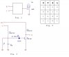
Hello, I am trying to make a circuit for my motorcycle. This will be my first project and I have some questions. This circuit will be for a extra light I plan to add. I will have a light for each side of the bike and it will be red so I will make two circuits, one for the right, one for the left. This light only has one bulb so i have to make a circuit that when the turn signal comes on it becomes a turn signal and blinks, when the brake comes on it becomes a brake and stays on, but if the turn signal comes on and the brake comes on it will work as a turn signal and not a brake. I think I figured out what parts I need I just have to do the math ( that is very confussing). Do you think it will work once I do the math. The second question is can I send 12 volts threw the collective side of the trasistor? why or why not? This is my first project and for a 17 year old I am really excited to see if I set the componets up right. thanks, sorry for the sloppy diagram i did the best i could do.For the not gate/inverter i am using the chip 7404.
B=brake light
T= turn signal
O= out to light
 

Attachments

  • a.gif
    a.gif
    2.4 KB · Views: 856
Are you guys confused on what Im trying to do, is my diagram really mesed up. I am starting to feal that no one will respond and that I will not be able to do this
 
A couple of questions:

1. Is this going to be your only flasher, or is this goign to be on top of an existing flasher?

2. Are you going to use a mechanical flasher unit, or are you planning to go all electronic. They work in different ways. For example, electromechanical flasher units work in series with the bulb, and does not require separate supply lines.

Also, when implementing this, careful consideration should be given to the fact that the supply line is far, far from ideal. It hs wildly varying voltage (depending on the rev of the engine); it has large spikes (would kill a standard voltage regulator in no time), and moreover it also has negative spikes (must be clamped properly).

Jem
 
I thank both of you for your time and help, Siebei ( hope I spelled it right) I don't think I can because i am tring to make 1 light me a left hand turn signal and a brake ( the bike already has a seprate turn signal circuit and a brake circuit) as for the other questions 1) I don't know what "on top of existing flasher" Means but in the diagram T= the turn signal and will get a input of on off on off on off and so on the input will be the same as a input to a regular car turn signal 2) the bikes exsisting flasher as for the supply line why can't i use the motorcycles power you can use it to power radios, a cb, walkman, and cell phones with no problem just like a car. hope this helps you help me because i am one excited newbe with alot of learning ahead of me. Do you understand what i am trying to do with my circuit above :( thanks once again
 
I think I understand what you are trying to do, but I'm afraid your diagram does not make sense to me. :(

Is there no chance of using two lamps in each circuit, one for brake and one for turn signal? Or...allowing the single lamp to be turned on by the brake or turn signal would me much easier. The main problem I see is that if you are braking with your turn signal on at the same time, your circuit will have to have some means of waiting for the Off period of the flasher before it lets the brake signal resume control of the lamp. Do you understand what I mean?
 
Here is my take on this. Referring to the attachment, Fig. 1 is what I think you need. Fig. 2 is the truth table for what you need. In fig. 2, D is a signal that is high when the flasher is "engaged" (either left turn or right turn). F and B are you signals as described previously, and L is the lamp signal (1 means ON). Don't worry about how D is derived for now. From the truth table, you cna see that when D is 0 (no flasher engaged), the lamp signal follows the brake signal regardless of the F signal). When D is 1, the lamp signal follows the F signal regardless of the state of B.

Now, how do we derive D. The best way is to use a retriggerable positive- edge triggered monostable. Set the monostable period to be a bit more then the high period of the T signal. If the flasher is flashing, then the monostable will get retriggered before it times out, and the output will be a constant high for as long as the flasher is flashing. As soon as the flasher stops flashing, the output turns low.

If you are willing to experiment a bit with values, you can get by using the ciorcuit in Fig. 3. In this circuit, everytime the flasher is high it chrages the capacitor. When it is low, the capacitor discharges through R2. If there is enough voltage across the cap, the transistor collector will be low. It will turn high when the flasher turns off. You will notice that the D signal is inverted wrt to teh truth table. This can easily be remedied.

So, now you have your D, T, and B signals. You can now proceed with the logic design, and power driver. Before going further, do you think that this is what you were asking for? Secondly, is it enough for you to work on?

Don't know exactly what your electrical level is. Don't want to take the fun out of it completely for you. However, I am willing to help.

Jem
 

Attachments

  • Flasher_1.jpg
    Flasher_1.jpg
    61.7 KB · Views: 844
  • Flasher_1.jpg
    Flasher_1.jpg
    61.7 KB · Views: 821
sorry but the last post i did not under stand. below is a truth table. t= is a sorce that you would plug a light into if you were hoking it up as a turn signal so when turn signal is on it goes 0 1 0 1 0 1 ect till turn signal is turned off and b= is a source that you would plug a brake light into ( when brake is on will supply constat power till brake is released. i know this device exsists because they use it for trailers because they only have 1 light for each side and so the one light has do be a brake light and a turn signal. and they get the currents off you car's brake light, and turn signals thanks o=on 1=off

T B output acts like
0 1 brake lite
1 0 turn signal
1 1 turn signal
0 0 nothing, out put 1
 
andrew8485 said:
i know this device exsists because they use it for trailers because they only have 1 light for each side and so the one light has do be a brake light and a turn signal.

On all trailer lights I've seen, that one lamp on each side is dual filament...one for brake and one for turn. I'm sure this project can be done but it seems like a complication of a simple problem.
 
One more time...

Is this what you want? That is, have an additional set of lights (one for Brake/Left turn, and one for Brake/Right turn) on top of you existing arrangement.
 

Attachments

  • Flasher2.jpg
    Flasher2.jpg
    95.9 KB · Views: 660
Thanks! I was trying to implement a very crude comparator. The diode just increases the threshold of the comparator, by adding to the VBE of the transistor. Otherwise, you would need a very big capacitor if it only has to charge to a small VBE threshold before the transistor starts conducting. Note that even while the transistor is is conducting, the capacitor still gets charged, but at a lower rate since the charging current is shared between IB, and charging the cap. During the off period of the flasher, the capacitor quickly discharges through its parallel resistor and the base of the NPN until the voltage drops below the "threshold". Then the main discharge path is the parallel resistor.
 
Status
Not open for further replies.

Latest threads

New Articles From Microcontroller Tips

Back
Top