Continue to Site

Welcome to our site!

Electro Tech is an online community (with over 170,000 members) who enjoy talking about and building electronic circuits, projects and gadgets. To participate you need to register. Registration is free. Click here to register now.

  • Welcome to our site! Electro Tech is an online community (with over 170,000 members) who enjoy talking about and building electronic circuits, projects and gadgets. To participate you need to register. Registration is free. Click here to register now.

Bradycardia and Tachycardia Sensor

Status
Not open for further replies.

GP12

New Member
Hi! I need some ideas for my bradycardia and tachycardia sensor. It is part of a university project for an incubator prototype, it has to activate some kind of alarm (buzzer or LED) whenever the baby's pulse is not between the normal pulse range. The parameters that I have to take into account is that, for a baby, bradycardia occurs below 80 bpm and tachycardia above 150 bpm, that is a given fact that the sensor shall detect. My basic idea is to use a pulse sensor made from an IR and a phototransistor that will give a signal in a certain frecuency. I did some research and what most people do is to connect that pulse sensor to an amplifier to increase the signal, then it is filtrated by an active band pass filter and finally it is amplified one last time and it gets to an Arduino. I CANNOT USE ANY KIND OF DIGITAL CIRCUIT, JUST ANALOG. My idea is that if I make a band stop filter, instead of a band pass filter, I can eliminate the frecuencies in which the baby is okay, so if in any case the pulse goes out from the range the filter will give a signal. Then, I was thinking of connecting the resultant signal of the filter to a comparator made form op-amp. In which case will have the function of activating the alarm. If the frecuency is in the range (1.33Hz - 2.5Hz) it will not activate the alarm, if the contrary happens, it will activate the alarm. I'm not pretty sure if it will work or if it's another way to do it. As I said, I'm not allowed to use Arduino or something related to digital electronics. I attached my circuit, thank you!
 

Attachments

  • Schematic_Proyecto_C2_Sheet_1_20200326014554.png
    Schematic_Proyecto_C2_Sheet_1_20200326014554.png
    66.5 KB · Views: 161
It looks like your schematic was drawn with Texas Instruments TINA. Just replace your phototransistor with a signal generator icon.

Add a voltage meter after each filter and monitor those with the simulator's oscilloscope.

then adjust the frequency of the signal generatorfrom Bradycardia to ok to tachycardia ranges (in Hz) and monitor the output voltages to see if they do what you want them to do. Move the voltage meters to different op amp outputs until everything works. It is called a simulator for a reason - TINA simulates.
 
It looks like your schematic was drawn with Texas Instruments TINA. Just replace your phototransistor with a signal generator icon.

Sorry, it was not. It was made in easyEDA, but I have simulated the circuit and it works, but when I tried it in breadboard it didn't do what I expected. So I was wondering if the pulse sensor does give a certain frecuency when working. Also, I'm not sure if the 60Hz frecuency will affect in any way to the circuit as I planned. Thank you so much in advance.

Just a thing, I'm not sure if it does give a frecuency because I don't own an oscilloscope and the quarantine keeps me in my house. Where I live is mandatory quaratine, kind of a curfew. Thanks a lot.
 
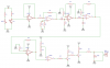
Your concept of using a band stop filter in cascade with an amplitude detector makes sense in theory, but there are a number of problems to solve. The primary one is of the bandstop filter. The filter that you show in the schematic appears to be a single pole high pass filter followed by a single pole low pass filter. While this configuration is ok for a bandpass, it will not work as a band stop filter. The reason for this is that the first filter, in this case the high pass, will, in theory, remove the spectrum below 2.5 Hz. So, only spectrum above 2.5 Hz passes to the second filter, the low pass. The low pass only lets through spectrum below 1.33 Hz, but you have already eliminated that with the preceding filter. So, in theory, nothing gets through. The correct way to configure this is to feed signal to both filter stages in parallel, and then sum the outputs of the two filters in the following op-amp. Check the schematic in this link: **broken link removed** .

The next problem is that these two filters, being only single pole each, have a frequency response with a very slow change in attenuation. Their output changes only 6 dB per octave. So, for example, the filter meant to low pass spectrum below 1.33Hz will only attenuate energy spectrum at double that frequency by 6dB, which is a voltage ratio of only 0.5. Similarly the high pass filter's response at 1.25Hz will be 0.5 in voltage terms. Even when wired correctly, this filter will have an extremely shallow and virtually useless stop band. To make this configuration work much better, you will have to increase the order of each filter, perhaps to 5 or 6 poles. In the past, when faced with this type of problem, I have used a switched capacitor filter IC with success (the TI MF10-N), but it is debatable if this is truly an analog IC or not.

Another problem with your circuit is more a practical one, and that is that you have not biased your op amps correctly. I believe that it is your intention that the first five op amps should operate in their linear region for the entire swing of the input signal. However, the three amplifiers following C1 are all biased to 0 volts DC. As a result, they will only amplify the upper half of the AC voltage swing that comes through C1. I don't think that this is what you intended.

Another potential problem is that you are limiting the voltage presented to SG1 to a maximum of the LED2 forward voltage, which may be somewhere between 1.2 and 3 volts. You should probably move SG1 to connect directly to the collector of Q3 if SG1 requires 5V to operate.

Another problem, or perhaps I don't quite understand the circuit, but I don't see anything that prevents the buzzer, SG1, from buzzing on and off at the rate of the patient's heartbeat. Is that your intention? I would think that you would want to detect the presence of tachycardia or bradycardia and then turn the buzzer on steady, not pulsing like that.

I would also recommend that it will be necessary to allow the operator to tune the amount of signal picked up at Q1 in order to adjust to different patients and different sensor positioning from one to the next. Perhaps simply making R1 partially adjustable can do this adequately.

I think there is a strong chance that the circuit will be interfered with by 60Hz, 120Hz and possible other frequencies from LED lighting. One way to avoid this would be to include yet another filter in the signal path to attenuate those frequencies. A low pass set to 10Hz or so might be appropriate. A more sophisticated way of handling this problem is to modulate the IR transmitter to some frequency that is free of local interference, and then use a receiver with a narrow band pass frequency response to detect the IR that is passing through the patient. Some systems use 40KHz as the modulation frequency. I believe that this is an advanced concept that you should ignore until you get your basic idea working first.

In order to understand these limitations, fix the bias problem on your circuit first. You can do this by disconnecting pin 4 of each LM358 and connecting them instead to -Vcc (ie minus 5 volts DC). This will require another power supply. There is a way to fix this and retain the use of only one power supply, but it is slightly more involved. You would have to disconnect R7, R8, R11, and R13 from ground and connect of them them instead to a steady source of one half Vcc.
 
Last edited:
I would
1) amplify the heart beat from the LED into a saturated square wave with a high gain op amp circuit.
2) connect a cap in series to the (+) input of a second op amp. Add a 2k resistor from (+) input of 2nd op amp to ground to create a short pulse from op amp 1 to op amp 2

3) connect a diode to the output of op amp 2 (add a cap and resistor to creat a peak detector that keeps draining itself.
This create a sort of missing pulse detector - the voltage of the cap will fall more if the next heart beat pulse does not come soon enough. This can be tuned very accurately in time. The high gain, square wave in the first stage eliminates any issues with voltage varying with each heartbeat or variations in sensor sensitivity.

4) connect op amp 2's peak detector to an op amp used ass a comparitor. The op amp will power the buzzer for the gap in time - it becomes very urgent sounding and will initiate a response

I'll let you tune the voltages, timing and use the same concept to figure out the tachycardia sensing.
B7F9E5FD-1BC8-4DB9-ADBB-FDBC1E4B94B8.jpeg
 
Status
Not open for further replies.

Latest threads

New Articles From Microcontroller Tips

Back
Top