Continue to Site

Welcome to our site!

Electro Tech is an online community (with over 170,000 members) who enjoy talking about and building electronic circuits, projects and gadgets. To participate you need to register. Registration is free. Click here to register now.

  • Welcome to our site! Electro Tech is an online community (with over 170,000 members) who enjoy talking about and building electronic circuits, projects and gadgets. To participate you need to register. Registration is free. Click here to register now.

Bosch battery charger

Status
Not open for further replies.
I have not yet worked out exactly how it works but it MAY need to see at least 5 volts from the battery to be charged before starting to work.

Les.
Thanks Les. That's an interesting thought. So I'll temporarily reassemble it & see if it
After a bit more research, I suspect the MCU is probably an ST6200 series one - 16 pin types with power on pin 1 are very scarce; that fits plus the RC osc is pin 3 and pins 7/8/9/10 have analog input capability, which also matches your sketch.
(Though I think the connections around pins 5 & 6 may be messed up?)

Data:
You're right about pins 5 & 6. 6 is in fact open, i.e. not connected to anything. 5 is connected to 0V, I have attached a revised circuit.
 

Attachments

  • Charger cct.jpg
    Charger cct.jpg
    1,018.3 KB · Views: 864
Looking at it again, I think it uses PWM from pin 14 of the MCU to control the input power.

It may not do anything much other than idle until it recognises the battery type and required voltage from the NTC, COP and battery voltage, then presumably tries to maintain an appropriate constant voltage - with no current limiting??

What type of batteries is this for - NiCd / NiMH, at a guess?

Also can you double check the 100n cap connection - does it really go to pin 3? The MCU in the data should only have a resistor on that pin.
 
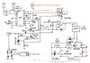
Looking at it again, I think it uses PWM from pin 14 of the MCU to control the input power. That sounds reasonable. I would need to fire up my scope to prove it. However, the scope is not working very well. I think it may need a firmware upgrade.

It may not do anything much other than idle until it recognises the battery type and required voltage from the NTC, COP and battery voltage, then presumably tries to maintain an appropriate constant voltage - with no current limiting?? I think NTC may go to a thermistor inside the battery that has a negative coefficient.

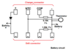
What type of batteries is this for - NiCd / NiMH, at a guess? It is a Li-ion battery.

Also can you double check the 100n cap connection - does it really go to pin 3? You're right. It & the 47 k go to pin 5. I must have counted from the wrong end when looking at the copper side of the PCB. The MCU in the data should only have a resistor on that pin.
Thanks for your continuing interest. See my comments in red above. Here is the revised circuit. The 100 nF Is a bypass. I had wondered why there was no bypass.

Charger cct.jpg
 
Last edited:
The question about the type of battery type the charger was designed for prompted me to look at the picture of the charger. That confirmed it was for Li -ion batteries. The fact that it states the voltage range is 14.4 to 21.6 means it must be designed to cope with 4 cell and 5 cell batteries. This means it will have to sense if the battery is 4 cell or 5 cell. I think it must first measure the battery voltage first. (Possibly after a period of very low current charging.) I am making the assumption that it is unlikely to be the microcontroller that has failed. (As in my experience I have never seen one fail.) I am still having difficulty fully understanding how the primary side works. Are you sure that you have MT1 and MT2 the correct way round on your drawing ? What is the rated working voltage of C3 ? .On the secondary side U2b seems to sensing the battery voltage ( 1/11 of the battery voltage.) and comparing it with a number of different reference voltages stet by the outputs on pins 13 and 14 of the micro and a network of resistors. I assume this is to shut down charging when the battery reaches a certain voltage. this would suggest that that turning on the LED in the opto isolator shuts down the primary side. (It could also be the other way round in that it will not fully enable the primary side unless the initial battery voltage is above some preset value.) It is a bit odd that there is no current limiting resistor between the output of U2b and the opto.

Les.
 
Thanks again Les. I accidentally omitted the resistor in series with the LED when I drew the diagram from a rough sketch I made while tracing the circuit.
It is a 1k.
It's getting late here so I'll answer your other questions tomorrow & post the revised circuit.

I'll have to remove C3 from the PCB as its cap & voltage are hidden by C4. Then I'll also be able to read the value of C4.
 
I wonder if COP is Current output - as in, there is a current sense resistor within the battery pack? It would have to be between battery negative and the 0V terminal.

Can you measure the resistance from COP and NTC to the 0V/negative terminal on a battery pack?
 
The question about the type of battery type the charger was designed for prompted me to look at the picture of the charger. That confirmed it was for Li -ion batteries. The fact that it states the voltage range is 14.4 to 21.6 means it must be designed to cope with 4 cell and 5 cell batteries. This means it will have to sense if the battery is 4 cell or 5 cell. I think it must first measure the battery voltage first. (Possibly after a period of very low current charging.) I am making the assumption that it is unlikely to be the microcontroller that has failed. (As in my experience I have never seen one fail.) I am still having difficulty fully understanding how the primary side works. Are you sure that you have MT1 and MT2 the correct way round on your drawing ? What is the rated working voltage of C3 ? .On the secondary side U2b seems to sensing the battery voltage ( 1/11 of the battery voltage.) and comparing it with a number of different reference voltages stet by the outputs on pins 13 and 14 of the micro and a network of resistors. I assume this is to shut down charging when the battery reaches a certain voltage. this would suggest that that turning on the LED in the opto isolator shuts down the primary side. (It could also be the other way round in that it will not fully enable the primary side unless the initial battery voltage is above some preset value.) It is a bit odd that there is no current limiting resistor between the output of U2b and the opto.

Les.
Thanks again Les. Yes, I had MT1 & 2 transposed. I've fixed that and made a few other changes to the circuit.
I removed C3 so I could test it and read the values of C3 & C4. C3 is 10uF 100V & C4 is 47nF.
I opened a battery that has been dead for several years & traced the circuit. See the second attachment. U1 can't read the battery voltage due to the diode.

So it appears that the resistor connected to COP in the battery is chosen according to the battery voltage. Hence U1 reads this voltage & acts accordingly.
As I thought, NTC is connected to a thermistor inside the battery. It was 7.68k at ambient temp, so I put it out in the Sun for about 35 min. The batteries were so hot that could barely hold them (summer starts next month). The resistance was 4.2k.

I had accidentally omitted the 1k resistor in series with the Opto LED. It was on the rough sketch I drew while tracing the circuit but I missed it when drawing it up a bit neater.

Tomorrow, I intend to test the Opto. Then I'll turn the power on & connect a 6.2k resistor to the COP spring & see if the voltage between the + & - springs changes. If not, I'll measure the voltage across R3 with a true RMS meter. That should tell me if the high voltage side is working. Thanks for your continuing interest.
 

Attachments

  • Charger cct.jpg
    Charger cct.jpg
    994.1 KB · Views: 721
  • Battery cct.png
    Battery cct.png
    26.8 KB · Views: 632
OK, I'd try connecting the resistor to COP and one to NTC as well, around 6 - 7K

It should have some effect on the output voltage?
 
Thank
I wonder if COP is Current output - as in, there is a current sense resistor within the battery pack? It would have to be between battery negative and the 0V terminal.

Can you measure the resistance from COP and NTC to the 0V/negative terminal on a battery pack?
Thanks again. See the previous post. There is no series resistor. It appears that the controller determines when the battery is fully charged by the temperature.
I have no idea what COP stands for.
 
This is my limited theory of how the primary side works. First just consider R1, C2, The diac and the triac. This is just the same as a simple light dimmer. I think with the value of C2 and R1 the triac will switch on fairly early in the cycle giving a reasonably high output from the transformer. Now consider when the output of the opto is conducting. In that state you could consider the two diodes to behave almost like a short circuit and the 2.7 ohms of R3 will not have much effect. So C1 and C3 in series will be in parallel with C2. This will cause the triac to be triggered much later in the cycle giving a lower output from the transformer. If the primary current gets high enough so give a volts drop of more than about 0.6 volts across R3 then the transistor V5 will start to conduct discharging C3. I don't see that this would cause a significant change in the trigger angle. When the opto was not conducting C1 and C3 in series would be charged to a voltage just above the diac trigger voltage. One the capacitors were charged they would have no effect on the trigger angle. (This is ignoring any very slight self discharge of the capacitors due to leakage.) In this state the trigger angle would only be controlled by R1 and C2.

Les.
 
Thanks Les. I measured the voltage across R3 & it was 33mV RMS. So, obviously, the TRIAC Is not conducting.

I had tested it with my component tester & it was OK. So it had to be the DIAC.

I tried to remove it from the PCB but it was proving difficult. So I applied a little pressure on the wire with a screwdriver & the DIAC broke.

It was glued to the PCB by what ever they sprayed it with. I was hoping to be able to read what was on the underside of the DIAC in order to find a data sheet. But it's now unreadable. There was E80 on the top & all I can see underneath is 7. The remaining letters/numbers were lost (stuck to the PCB).
Had I been able to extract it whole, I was intending to set up a simple test rig to determine the trigger voltage & thus prove whether it was faulty.

I have not used a TRIAC. DIAC in any of my designs & thus know little about them. Do you know what trigger voltage I need?
 
I don't think you had enough evidence to conclude the diac was faulty. I would have first checked the input and output of the opto isolator to try to get an idea if the fault was on the primary or secondary side of the transformer. I don't think there is a way to find out what the breakover voltage was. If it was just on a light dimmer I don't think it would be critical but it may be important in this charger. If there was 33 mV across R3 then the triac must have been conducting for a few degrees near the end of each half cycle. If it had not been conducting at all the current would have only been about 1 mA (Via the 200K resistor.) 33mV means the current was about 12 mA

Les.
 
Last edited:
Thanks Les, You may be right, but I measured the voltage across R3 today with no DIAC & it was 20 mV. My calculations indicate it would be about 3.3 mV if the TRIAC was not conducting. So I don't know where the extra 17 mV is coming from. I have not had much time today the explore further as we are helping our daughter & granddaughter to move to a new house. We'll be doing more tomorrow.

The opto only has an effect on positive half cycles when D1 conducts. It looks to me that C1 is charged from C3 at a constant current via the opto.
On negative half cycles, C3 is charged via C1 & D2. When V4 triggers, V5 is turned on & it discharges C3.

When I have time, I'll insert the new DIAC & see what happens.
 
V5 will only turn on when the current through R3 creates a voltage of more than about 0.6 volts across it. This would be a current of about 220 mA. I also think you should have a battery connected to the charger as without it there is no smoothing on the output of the bridge rectifier. So the 5 volts rail will be dropping to zero at every zero crossing of the AC input.

Les.
 
V5 will only turn on when the current through R3 creates a voltage of more than about 0.6 volts across it. Yes, I understand that. This would be a current of about 220 mA. I also think you should have a battery connected to the charger as without it there is no smoothing on the output of the bridge rectifier. So the 5 volts rail will be dropping to zero at every zero crossing of the AC input.

Les.
Thanks, that's a good point. I'll connect an electrolytic as a temporary measure since I would have to reassembly the charger in order to connect a battery.
 
Status
Not open for further replies.

Latest threads

Back
Top