Continue to Site

Welcome to our site!

Electro Tech is an online community (with over 170,000 members) who enjoy talking about and building electronic circuits, projects and gadgets. To participate you need to register. Registration is free. Click here to register now.

  • Welcome to our site! Electro Tech is an online community (with over 170,000 members) who enjoy talking about and building electronic circuits, projects and gadgets. To participate you need to register. Registration is free. Click here to register now.

Boost converter how?

Status
Not open for further replies.

Pommie

Well-Known Member
Most Helpful Member
In the RE section we are trying to get some kinda pic based charge controller working. I can do the code but need some help with the boost topology.

As an initial step I'd like to use a 20W panel I have and boost the output to charge a 12V battery. The idea is that on a dull day the panel may be most efficient at 8V. The voltage it is most efficient at is not important, we simply measure the current going into the battery and adjust the duty cycle for a maximum.

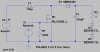
So, the question, given that the pic will produce a PWM frequency of around 72kHz, what would be required to boost the input from say 2-12V to 14V at a current of up to 2A?

I think what I am asking is, given a 72kHz 50% signal, what will produce roughly 14V out given 7V in? Also, will a pic be able to switch a logic level mosfet at 70kHz without a buffer. (A pic pin can source/sink 25mA so I'm guessing a buffer will be needed)

Sorry for so many questions, never done any smps stuff before.

Mike.
 
hi MIke,
I know this dosn't answer your query directly, but it may prove useful as a background document in your quest.:)
 

Attachments

  • SMPSRM-D.PDF
    804.5 KB · Views: 688
Whether you need a buffer to drive the MOSFET depends upon the gate capacitance of the particular MOSFET you are going to use. The rise and fall times are roughly t = Q/I where Q is the total gate capacitance charge (usually given on the MOSFET data sheet) and I is the gate drive current (for the PIC this is 25mA). You probably don't want the rise and fall times to be greater than a percent or so of the switching period for maximum efficiency.
 
pommie, have you read about MPPT charge controllers?

I was pondering charging a 12v battery from a pair of 5w panels I purchased some time ago. They output about 21v open circuit and they're spec'd to put out 300mA at 15.5v, but connecting them directly to various 12v@7ah gelcel batteries I see 18v at 100mA (strange that the battery is not pulling the voltage down). I had considered building a pic that would charge a large cap and dump it as pulses into the battery, disconnecting the cap from the battery as the cap voltage dipped below 13.5v.

it has been my observation high voltage boost converters seem to use low power high inductance coils, where as high current boost converters using high power low inductance coils. I'm not sure where the balance would be for your application, but why not just pick what you've got in the parts drawer and start there, something 100-330 uH. Since you're building a "digital smps", you can make up for a lot of variables that dictate the inductor selection in analog control / regulator chips. For example, you can always skip cycles, or adjust the switching speed trying to find the input to output 'sweet spot'.
 
I've worked on commercial solar MPPT. It's really not worth doing for 12v in 12v out (which is why you won't see many 12v MPPT units on the market).

You end up with a buck converter changing the solar panel peak power output at 16v (maybe 17v) into 13.8v or 14v output (to the battery), and even with a good efficient SMPS MPPT design a 16v to 13v converter is not that efficient and you will only get a few percent more power into the battery if anything extra at all. Some of the amorphous solar panels make their peak at about 15v so they are just not MPPT compatible anyway.

On a 24v or 48v system they can be worth the effort, but rarely on a 12v system. You might get better power gains by more regular cleaning of the panel or better panel orientation that you will get from a 12v MPPT.

Pommie, why do you need to convert 8v up to a 12v battery?? Is your 20w panel a 6v one?? Have you obtained a power output chart for V/I for your panel to see it's power output characteristics?
 
...

I was pondering charging a 12v battery from a pair of 5w panels I purchased some time ago. They output about 21v open circuit and they're spec'd to put out 300mA at 15.5v, but connecting them directly to various 12v@7ah gelcel batteries I see 18v at 100mA (strange that the battery is not pulling the voltage down). ...
You have junk batteries. They have been sitting around so long that they have sulphated, and will not take a charge. I'll bet that you would see the same result if connected a current-limited lab supply set to 18V o.c with the current limit set to 100mA to the batteries.
 
Last edited:
The only reason to use the 20W panel is because I already have it. It is a 12V panel and I was just guessing that on a dull day it might be most efficient at 8V. As it happens, I also have two batteries I could wire in series to use. The idea is to get some hardware to use as a test bed so the software can be written.

@JustDIY, yes, that is what is hopefully going to come of this.

Mike.
 
I got around to having a play in Switcher Cad.

For the solar panel I used a 21V source with a series resistance of 5Ω.
For the battery, 2 x 12V zeners and a 0.1Ω resistor.
I pulsed the gate with a voltage source at 70kHz with a series resistance of 40Ω. Plus 2k resistor to turn it off.

It seems to work, input is around 12V 1.8A and output is 26V 0.6A.

Anyone any comments or suggestions before I build this?

Is a BUZ71 suited to this? With a gate threshold of 3V I'm hoping it can be switched with the pic output.

Mike.
 

Attachments

  • bat.png
    bat.png
    19.5 KB · Views: 686
I got around to having a play in Switcher Cad.

For the solar panel I used a 21V source with a series resistance of 5Ω.
For the battery, 2 x 12V zeners and a 0.1Ω resistor.
I pulsed the gate with a voltage source at 70kHz with a series resistance of 40Ω. Plus 2k resistor to turn it off.

It seems to work, input is around 12V 1.8A and output is 26V 0.6A.

Anyone any comments or suggestions before I build this?

Is a BUZ71 suited to this? With a gate threshold of 3V I'm hoping it can be switched with the pic output.
If you notice the data sheet, the BUZ71 requires 10V to fully turn on and achieve its 0.1Ω rated "on" resistance. It's only conducting 1mA at the threshold voltage. You need a logic-level MOSFET if you want to drive it with 5V.
 
Ahh, hadn't looked at the datasheet, just saw the gate threshold in a table and assumed - must remember, it's dangerous to assume. Guess I'll order a few IRL540 unless anyone has any better suggestions?

Mike.
 
Whether you need a buffer to drive the MOSFET depends upon the gate capacitance of the particular MOSFET you are going to use. The rise and fall times are roughly t = Q/I where Q is the total gate capacitance charge (usually given on the MOSFET data sheet) and I is the gate drive current (for the PIC this is 25mA). You probably don't want the rise and fall times to be greater than a percent or so of the switching period for maximum efficiency.

as the mosfet is running at up to 14 V and the pic 5 V some duffer/driver whatever is a good idea TC1426/7 are quite good and cheap for this, I've been using a TL082/4 opamp
 
Just ordered some IRL540s and some TC1427s.

Thanks,

Mike.

Gday Mike,
See that you are LTS user, you may find these helpful for the PV sims.
 

Attachments

  • Pommie1.zip
    5 KB · Views: 166
Hi Eric,

Yes, I like LTS, very useful. Tried downloading your file but it says the zip file is invalid.

Mike.
 
Hi Eric,

Yes, I like LTS, very useful. Tried downloading your file but it says the zip file is invalid.

Mike.

Hi,
Just done a test download, all ok.

Using the same zipper for other members posts, no reported problems.???
 
I downloaded it and opened it with 7-zip and it is fine. Stupid windows zip out of date I guess.

Do these files become new symbols? If so, where do I place them?

Thanks,

Mike.
 
It's still not worth making a buck switcher for 12v to 12v system. :(

If your 12v panel makes an open circuit voltage of 21v it's probably a crystalline type that produces peak power at about 17v.

On a 12v to 12v system you need to protect the panel with a reverse protect diode, even a decent schottky will drop about 0.4v and you will lose about 0.3v in wiring and terminations etc.

So with your panel at peak power output your SMPS will receive 16.3v input. Now assume your battery is at a nominal 13.8v operating voltage. You have a SMPS with 16.3v input and 13.8v output. Now if you can make a SMPS as good as the commercial one I designed you might get 90% efficiency at 16.3v->13.8v.

So that's (16.3 * 0.90) / 13.8 = current gain of 6.3%.

So you think "that's ok, it's still worth making the MPPT to get 6.3% more current into the battery".

But it's rarely worth it, because if the battery is close to full charge (over 14v) it won't produce much gain at all. Also, the max panel power is rated at say 20W (17v 1.17A) BUT if you connect to a lower load voltage the panel power is on a curve and it will make more current into a 13.8v load than it will into a 17v load.

See this curve, it's pretty typical;
**broken link removed**

So if you directly connect the panel to the 12v battery you will get about 6% more current into the battery because it is driving a lower load impedance, which is the same power output as you got from the MPPT.

I've already said it above, it's not worth doing on a 12v->12v system which is why there are practically no 12v MPPT devices on the market. And you completely ignored my post, you are asking for people who have experience to help and then ignoring them... :)
 
Last edited:
It's still not worth making a buck switcher for 12v to 12v system. :(

I've already said it above, it's not worth doing on a 12v->12v system which is why there are practically no 12v MPPT devices on the market. And you completely ignored my post, you are asking for people who have experience to help and then ignoring them... :)

Nope, I think you must have missed my reply to you and the part in my post where I stated that I have 2 batteries I can use to make it 24V. I also posted a circuit that is an attempt to make a 12-24V system. I did take on board what you said, did reply and did change my goal because of it.

Mike.
 
I've worked on commercial solar MPPT. It's really not worth doing for 12v in 12v out (which is why you won't see many 12v MPPT units on the market).

You end up with a buck converter changing the solar panel peak power output at 16v (maybe 17v) into 13.8v or 14v output (to the battery), and even with a good efficient SMPS MPPT design a 16v to 13v converter is not that efficient and you will only get a few percent more power into the battery if anything extra at all. Some of the amorphous solar panels make their peak at about 15v so they are just not MPPT compatible anyway.

On a 24v or 48v system they can be worth the effort, but rarely on a 12v system. You might get better power gains by more regular cleaning of the panel or better panel orientation that you will get from a 12v MPPT.

Pommie, why do you need to convert 8v up to a 12v battery?? Is your 20w panel a 6v one?? Have you obtained a power output chart for V/I for your panel to see it's power output characteristics?
Fine, I'll put in my two cents:

You seem to be neglecting the possability of it being a solar lighting app. Some of those see deep discharge on the batteries overnight after a cloudy day and a bright day following then would be bucking 17V into 10V (dead lead acid) for a gain of 70% with a 95% conversion efficiency possible.

And yes, it is possible with a properly designed switcher and a synchronous reverse polarity diode.

Dan
 
Last edited:
Whoops sorry Pommie! I was a bit hasty reading through the thread.

OK, if you want to make a 12->24v converter (which must require a SMPS) you may as well make it a MPPT to get the extra bit of power into the batteries.

The BUZ71 is way obsolete in terms of making high performance SMPS. There are many much better NFETs available. One of the good things about going 12v->24v boost is that you won't gain much from synchronous rectification so you can just use a schottky diode for the rect, which makes it a lot simpler.

To make it a MPPT boost circuit you need to regulate the switching to maintain the INPUT voltage, and keep that at about 17v. That will operate the solar panel at or near max power output. Then if you need the circuit to act as a battery charge controller you use a second system to shut it down when the battery is full, or keep it running and dump load when the battery is full.

You won't find many schematics for boost SMPS that regulate input voltage however. ;)

There's a couple of ways if you are using a PIC as controller;
1. make a fixed period ON pulse whenever the input rises above 17v, this will work fairly well in boost as the input voltage is constant and known, as is the input capacitance and the input current is constant
2. generate a PWM signal and monitor the input voltage and keep adjusting the PWM so that the input voltage remains at 17v (which has its own issues)

Ubergeek63- I agree that with a low load voltage a 12v->12v MPPT can be worth it. Driving 12v pump motors is another good example because the MPPT will make a lot more start current for the motor (when load volts are REAL low) than a panel alone will make, in that case you can use a smaller panel and/or remove the battery altogether.
 
Status
Not open for further replies.

Latest threads

New Articles From Microcontroller Tips

Back
Top