Hello all. This is my first post and I am a total newbie. I have done quite a bit of research over the past week, however.
This is my situation in a nutshell - I need connect a line level signal to a mic level and, more importantly, block the DC power coming from my Sony minidv camera's mic input.
Here are some diagrams I found:
**broken link removed**
and WITH attenuation:
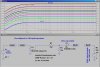
Line signal to microphone input
These are the specs on my camera's input:
Minijack, 0.388 mV low impedance with DC 2.5 to 3.0 V, output impedance 6.8kΩ (kilohms) ( Φ 3.5mm), Stereo type
According to this website a 1uf cap would do nicely (but I don't think using anything up to 10uf would be that wrong either):
**broken link removed**
Any way, let's forget about attenuation for the moment. I just want to block the DC power first. Here is what I did. I bought a variety pack of ceramic resistors (no polarity of course). I spliced a 3.5mm cable in half and connected 1uf capacitors in line with the red and black wires. Guess what? There is NO SOUND at all when I do that. What am I doing wrong? As soon as I remove the capacitors there is sound again.
It was suggested that I go to electrolytics and give it another shot. I will try this tomorrow but the puzzling thing is that this page:
Line signal to microphone input
specifically states "NOTE: The polarity of C1 is marked to the circuit in case you use an electrolytic capacitor. A "dry" plastic or ceramic capacitor is preferred in this circuit.
What the heck?
So, O Wise Electronic Masters, please advise this troubled soul on how to block a measly 3v.
This is my situation in a nutshell - I need connect a line level signal to a mic level and, more importantly, block the DC power coming from my Sony minidv camera's mic input.
Here are some diagrams I found:
**broken link removed**
and WITH attenuation:
Line signal to microphone input
These are the specs on my camera's input:
Minijack, 0.388 mV low impedance with DC 2.5 to 3.0 V, output impedance 6.8kΩ (kilohms) ( Φ 3.5mm), Stereo type
According to this website a 1uf cap would do nicely (but I don't think using anything up to 10uf would be that wrong either):
**broken link removed**
Any way, let's forget about attenuation for the moment. I just want to block the DC power first. Here is what I did. I bought a variety pack of ceramic resistors (no polarity of course). I spliced a 3.5mm cable in half and connected 1uf capacitors in line with the red and black wires. Guess what? There is NO SOUND at all when I do that. What am I doing wrong? As soon as I remove the capacitors there is sound again.
It was suggested that I go to electrolytics and give it another shot. I will try this tomorrow but the puzzling thing is that this page:
Line signal to microphone input
specifically states "NOTE: The polarity of C1 is marked to the circuit in case you use an electrolytic capacitor. A "dry" plastic or ceramic capacitor is preferred in this circuit.
What the heck?
So, O Wise Electronic Masters, please advise this troubled soul on how to block a measly 3v.