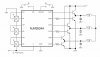
Hello, I'm creating a BLDC controller for a 12 volt Moog motor which pulls about 8.8 amps at full load. The sensor section motor itself has a Vcc input and three sensor outputs. I'm wanting to control it with a NJM2624A, but that chip has a rather unusual (IMO) hall sensor section where it has an individual input/output and comparator for each sensor. So my first question is can I bridge the +V across the comparators for the VCC of the motor, or will I simply not be able to use this particular chip?
My second question about this schematic has to do with the capacitors by the power transistors. I assume those are a snubber circuit, but I was wondering what capacitance I should choose (and what voltage for that matter) seeing as how it seems like that would make a resonant circuit. Do I need to measure the inductance for the motor and find my desired frequency and find a capactor that's resonant, and if I do, will that create an unwanted voltage spike?
Thanks in advance for your answers!