Continue to Site

Welcome to our site!

Electro Tech is an online community (with over 170,000 members) who enjoy talking about and building electronic circuits, projects and gadgets. To participate you need to register. Registration is free. Click here to register now.

  • Welcome to our site! Electro Tech is an online community (with over 170,000 members) who enjoy talking about and building electronic circuits, projects and gadgets. To participate you need to register. Registration is free. Click here to register now.

Best way to Create A Colpitts Circuit

Status
Not open for further replies.

Parkourguy

New Member
Hello, I'm new to circuit design with general beginner knowledge into circuitry, signaling and systems. I would like to try on a project on constructing a RF circuit to generate an output of 10MHz square wave frequency with a 5 volt output. Ive done a bit of research and would think that a Colpitts Circuit with a NPN transistor would be the best way to achieve this. I would like to know other peoples opinion on this and what points I should cover on this. Thank You
 
You seem a little 'confused'?, what do you want the oscillator for? - you mention RF and Colpitts (which is fine) but then say you want 10MHz square wave which a Colpitts doesn't give you, and wouldn't really be considered 'RF' either (RF is generally sine wave, and what you get from a Colpitts).

Assuming you're wanting it as a clock oscillator?, then a 10MHz crystal and a suitable logic chip would be the way to go.
 
Welcome to ETO!
A square-wave signal contains umpteen harmonics, so a 10MHz one could spread a lot of interference throughout the RF bands. You will need to make sure that your oscillator is very low power and well screened if you don't want to risk being arrested for operating an unlicensed transmitter!
 
You seem a little 'confused'?, what do you want the oscillator for? - you mention RF and Colpitts (which is fine) but then say you want 10MHz square wave which a Colpitts doesn't give you, and wouldn't really be considered 'RF' either (RF is generally sine wave, and what you get from a Colpitts).

Assuming you're wanting it as a clock oscillator?, then a 10MHz crystal and a suitable logic chip would be the way to go.
Yes the goal was to make a clock oscillator, so then a logic gate oscillator would be the best way to approach this project? Thank You for clarifying the issues I had previously. Is there anything I should know about constructing a logic gate oscillator?
 
A few questions if you could answer for me would also be great. I heard that a schmitt inverter as the first inverter would cause frequency distortion, so a 74HC04 inverter would be the best option as the first and second inverter rather than a Schmitt inverter. Would that be the best way to creating this crystal oscillator?
 

Attachments

  • cmos logic gate oscillator.gif
    cmos logic gate oscillator.gif
    8.8 KB · Views: 235
That circuit should work fine with an HC04; you do need to be careful not to over-drive the crystal, hence the resistor in series.
I'd definitely not use a schmitt trigger with a crystal, only with an R-C osc.

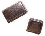
Or, you can just buy ready made clock osc modules - they are available in many formats and frequencies, they just need power and you get a logic level output - eg a common size 10MHz one.

Or a smaller package, 8 pin DIP size:
 
With the HC04 inverter oscillator, you may have to put a 1 Meg. resistor in parallel with the crystal in order to get it to work reliably.
 
Oops, I was looking on the wrong side of the inverter
 
It's obviously because you've been assimilated by the Borg! :D
That sounds like hard evidence of mind control.
(Reference to another thread).

JimB
 
There's still the Quadrature Borg, (hence my signature line), but there's a good chance that it's an imaginary group. ;)
 
Status
Not open for further replies.

Latest threads

New Articles From Microcontroller Tips

Back
Top