Continue to Site

Welcome to our site!

Electro Tech is an online community (with over 170,000 members) who enjoy talking about and building electronic circuits, projects and gadgets. To participate you need to register. Registration is free. Click here to register now.

  • Welcome to our site! Electro Tech is an online community (with over 170,000 members) who enjoy talking about and building electronic circuits, projects and gadgets. To participate you need to register. Registration is free. Click here to register now.

Best location for frequency counter...?

Status
Not open for further replies.

slimbo341

New Member
Good afternoon.

First time of posting.

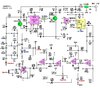
Attached on file is a circuit diagram I am building from a kit.

I wish to add a frequency counter, could you please advise best place to connect the live signal side. (Not Power).
I know the other side goes to GND.

Regards ... Dave.
 

Attachments

  • 50684-1.jpg
    50684-1.jpg
    76.6 KB · Views: 259
The data sheet suggests SA602 pin-7, then a buffer.
---------------------
Can't find a schematic but I think I built a 2 meter receiver with the counter connected to pin 7. (the count will be 10.7mhz off but that was fixed in the counter)
1628861654873.png
 
Last edited:
Thanks for your reply. The counter comes already pre built with only the 2 power wires and the 2 signal wires out putting off the pcb.

Would any other circuitry be required in this case do you think ..?

Regards ... Dave
 
Hi

Thank you very help . I think all the buffer circuit is pre built in the counter itself. I have no circuit diagram of the counter but has been bought as complete and ready to go.

My problem, which you may well have answered was just the location for the signal output. The rest is straight forward.

Will try this location when build is complete and get back on forum if this should not be the answer.

Once again many thanks ..... Dave.
 
Hi.

Just added picture of freq counter purchased in case of any more idea's.

Regards . Dave
 

Attachments

  • s-l1600.jpg
    s-l1600.jpg
    178.1 KB · Views: 228
The original circuit shows a 10uF capacitor between pins 6 and 7,

1628866114483.png


This can best be described as odd, I guess that the guy who drew that circuit intended to write 10pF.


Looking at the SA602 datasheet, we find various options for an oscillator:
1628866376456.png


Here, the writers of the datasheet (NXP Semiconductors) are showing how to connect the SA602 oscillator section to a synthesiser by tapping the signal at pin 7 of the SA602.
They also show a few options for buffer amplifiers to to prevent the synth from loading the oscillator circuit.

If the connection from pin 7 to your counter input is a short distance, it may be worth trying a direct connection, but be prepared for excessive loading and frequency shift when the counter is connected. In which case built one of the buffer circuits close to the oscillator and run a longer screened cable to the counter input.

But above all, don't forget to check that C11 on the receiver board is more like 10pF that 10uF.

JimB

PS, it looks like RonSimpson and I read the same datasheets!
 
Hi.

Thanks for your detailed reply.

I had already noticed the wrong value in C11 but forgot to mention it. Had already seen various similar circuits so I realised it was a whoopsie.

Not sure if the counter I purchased already has a buffer circuit built in, will have to try and find a diagram of said item.

A little bit difficult to place an addition board for the buffer as the SA602A unfortunately sits close to the middle of the PCB, and there is only fresh air around it. Will have to think on this. The receiver was never designed to accommodate a counter so its all a bit heath robinson.

While I appreciate the buffer circuit is small it still has be mounted somewhere as I do realise the shorter the wiring the better.

Many thanks for all your help.

Regards .... Dave.
 
I can't find the circuit but your frequency counter does include a buffer, you can see it in the top left of the component view (part of it is the second component in on the top row of components).
 
Morning.

Physical picture of populated board shows C11 as a small rated capacitor.
 

Attachments

  • ©─012375  (1).jpg
    ©─012375 (1).jpg
    277.9 KB · Views: 211
I think this thread is related to displaying of frequency of a receiver of some sort. The principle of hetrodyning means the local oscillator runs the desired frequency + or - an IF frequency. You get the sum and difference frequencies. For FM, this frequency is 10.7 MHz and for AM either 262.5 (I think) or 455 kHz.

So, if your listening to 101.1 MHz, the local oscillator is running at 101.1-10.7 or 101.1+10.7 MHz, There are "Frequency disply"kits avaiolable thhat allow you to set these offsets finer than the exact 10.7 or 455. I'd really suggest you look for one of those.
 
KISS,

The receiver is for the VHF aircraft band, so it receives AM and the IF frequency is 10.7MHz.
Whether the local oscillator is set for high side injection or low side injection is not explicitly stated.

JimB
 
I think the frequency displays still work.

We think AM/FM band but also Amplitude Modulation and Frequency Modulation. Then you get the wierd stuff, Sidemands and FM Stereo and 8VSB etc.
 
Status
Not open for further replies.

Latest threads

New Articles From Microcontroller Tips

Back
Top